
[Buying guides]
Automatic Capping Machine: Line Integration and Torque Control
Poor cap engagement wastes filled bottles. Match an automatic capping machine to the closure, bottle restraint and cap feed, then define torque checks and line interfaces before comparing output.
Updated October 2026
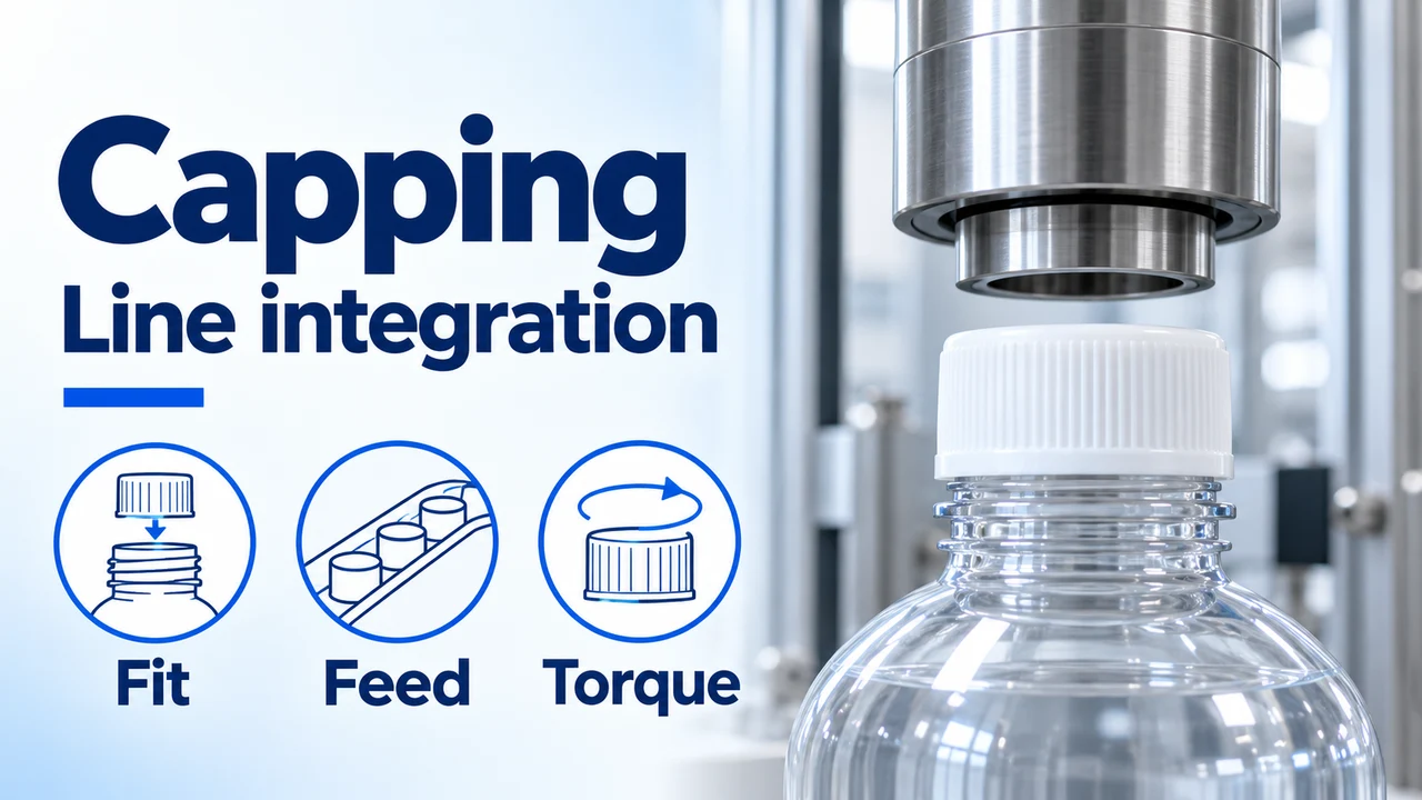
Inputs that decide the capping configuration
Scroll across to read all three columns.
| Input or item | Typical value or source | Why it matters |
|---|---|---|
| Cap-to-neck attachment | Closure and neck drawings | Selects threaded tightening or press-on closing. |
| Torque or seating limits | Packaging supplier specification | Defines what a correctly closed pack must meet. |
| Bottle stability | Filled bottle geometry and material | Determines restraint and transfer questions. |
| Accepted output | Your bottles/shift and format mix | Connects running speed with stops and rejects. |
| Cap supply and interfaces | Existing equipment and proposed scope | Separates the closing head from a complete automatic step. |
Start with the closure and the filled bottle
For an automatic capping machine, choose spindle or chuck tightening for a compatible threaded closure, and a press-on system for a snap closure. Then check how caps reach the bottle, how the bottle resists turning and how the closed pack transfers to labeling. We use those interfaces to discuss a bottle filling and capping machine as part of a line. This guide gives you a selection matrix and the fields to record before a proposal.
We build lines to order. The proposed capper, cap feed, format tooling, output and acceptance requirements must be defined for your bottle and closure; this guide supplies the decision framework.
Compare spindle, chuck and snap capping
Match the mechanism to the attachment between cap and neck. A hinged lid describes how a consumer opens a cap; the cap itself may screw on or snap on.
| Mechanism | Choose it for this closing action | Dominant Failure Mode & Prevention |
|---|---|---|
| Spindle capper | Pairs of rotating discs contact the outside of a screw cap as bottles travel through. Check accessible cap sidewall and bottle support. | Cap slipping or bottle rotation: review disc contact, wear and gripper position. Include the compatible cap delivery arrangement. |
| Chuck capper | A head grips the cap and rotates it over a supported bottle. Review the chuck and bottle tooling for each format. | Wrong engagement or an unsuitable chuck can damage or misapply a closure. Specify matched tooling and ask how torque is controlled and checked. |
| Snap / press-on capper | Downward application seats a closure designed to snap into its matching neck. Identify the actual attachment beneath a flip-top lid. | Incomplete seating: define the seated position and retention check with the packaging supplier; verify support under application load. |
A servo drive describes the drive system. Ask separately whether the proposed machine measures torque, records it or only follows a setting; feedback is not implied by the word servo.
Define torque limits before changing a setting
For continuous-thread screw caps, obtain the packaging supplier's application and removal torque requirements for the exact neck, cap and liner combination. Application torque is the tightening input. Removal torque is measured when opening the closed package after a defined interval. Record both with units and conditions rather than treating them as interchangeable.
ASTM D2063/D2063M-24 describes manual measurement of removal torque over time for matching continuous-thread packages under specified environmental conditions. The evaluation uses a known application torque and zero downward applied force during removal measurement. Use the agreed method and package limits when defining acceptance.
Our selection rule: if measured removal torque falls below the package supplier's lower limit, investigate seating, restraint and the agreed application setting before adding torque. If it exceeds the upper limit, investigate the setup before releasing packs. A supplier-defined window takes priority over a generic cap-diameter chart.
A leaking pack also needs the agreed leak check. A torque reading alone does not identify a damaged liner, contaminated sealing face or mismatched neck. Ask the closure supplier which inspection and leak criteria apply; record those separately from the torque result.
Keep the cap turning and the bottle steady
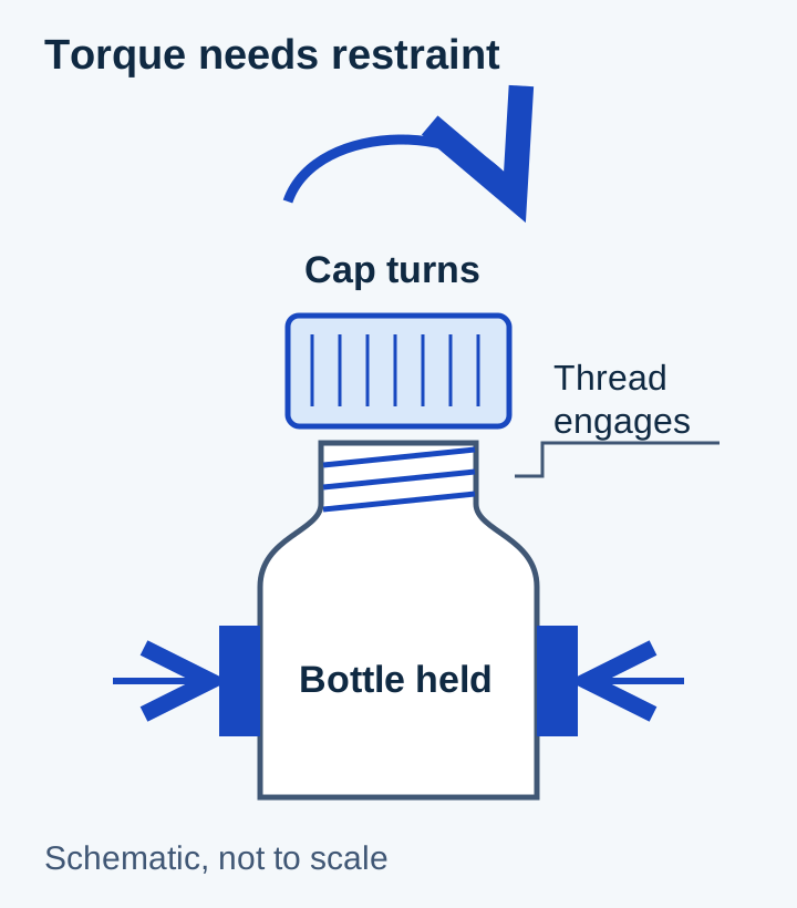
Write a torque and closure acceptance record
Agree the instrument, method, measurement timing and acceptance window before the run. Keep readings by head where the proposed configuration permits head identification.
| Record field | What to capture | Decision it supports |
|---|---|---|
| Package identity | Bottle/neck drawing revision, cap part number, liner and packaging batch | Keeps a different closure or material batch from being compared as the same package. |
| Application setup | Head or spindle setup identifier, format, running rate and torque setting or measured value | Separates a machine setting from a verified measurement. |
| Removal measurement | Instrument ID, units, elapsed time after closing, environmental conditions and individual readings | Makes later checks comparable against the agreed supplier window. |
| Closure condition | Seating, visible thread damage, cap position and the separate agreed leak result | Prevents an acceptable torque value from hiding a defective pack. |
| Disposition | Applicable limits, accepted/rejected result and action owner | Gives the line team a recorded release decision. |
Connect cap feeding to bottle arrival
Automatic tightening needs reliable cap presentation. Review the whole path: bulk cap supply, orientation, chute or pick-and-place transfer, cap placement and tightening. Confirm which steps are automatic and who replenishes closures. Pumps, triggers and dip tubes add handling questions that a flat screw-cap demonstration cannot settle.
Put the capper into the liquid filling line plan, including bottle condition at filler discharge. Foam or product on the neck, unstable bottles and an unsuitable transfer can affect the closure step. For a retrofit, identify the existing filler and conveyor rather than specifying only the new capper.
Where the two feeds meet
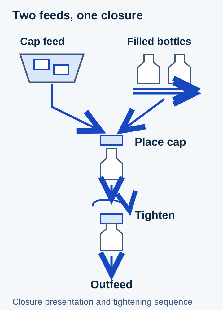
Agree interfaces and abnormal conditions
Treat these as requirements to agree, rather than assuming that every sensor, reject or control function is included.
| Interface | Question for the proposal | Acceptance situation to agree |
|---|---|---|
| Filler to capper | Who supplies the conveyor, transfer height, guides and bottle spacing? | Bottle arrives in the intended orientation without a transfer upset. |
| Cap supply to placement | Which closures can the sorter and delivery parts handle, and what changes between formats? | Low cap supply, missing cap and an incorrectly presented closure have defined responses. |
| Capper to downstream | Which machine sends ready, stop and full signals, and who integrates them? | A blocked discharge pauses the agreed upstream equipment and has a defined restart sequence. |
| Inspection and rejection | Are checks and a reject mechanism included, optional or supplied by you? | The agreed defective pack is identified and handled as specified, including the response if rejection fails. |
| Format change | Which chucks/discs, guides, belts and recipes change for every bottle-cap pair? | The team records the changed parts and checks the first packs against the same acceptance criteria. |
Calculate Accepted Output and Recovery Capacity
Measure accepted bottles and elapsed production minutes at the same count point. Accepted rate in bottles/min = accepted count / elapsed minutes. For station planning, compare supported running rates on the same bottle-cap format, then account for measured stop time and rejects from the same run.
Buffer positions for a constant arrival rate = incoming bottles/min × interruption seconds / 60. Use the observed stop duration and check the resulting count against usable positions, bottle stability and open-product waiting conditions.
With downstream rate above continuing arrivals, queue-clearance time in minutes = queued bottles / (downstream bottles/min − incoming bottles/min). Equal running rates keep an existing queue in place. Define the upstream pause and restart response where safe accumulation is limited.
Include the downstream labeling transfer
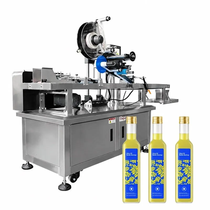
Leave room for caps, change parts and access
Use the line layout inputs to mark cap replenishment, removed format parts, conveyor transfers and access around the connected machines. Include the labeler's required bottle orientation after closure. A footprint comparison that omits these tasks can hide the space needed to operate the combined line.
Compare ownership cost over the same period
Use one common horizon, production quantity and format mix for each quotation.
| Cost or loss | Record over the chosen period | How to compare |
|---|---|---|
| Closure rejects | Affected bottle, cap, liner and product quantities; recoverable material separately | Multiply unrecoverable quantities by your own unit costs. |
| Changeover | Sum of measured changeover minutes during the period | Include cap feed, closing tooling and downstream adjustments. |
| Wear and service | Disc/belt/chuck parts and planned service labor | Ask for the proposed parts list and replacement basis. |
| Stop losses | Cap starvation, jams and rejected-pack handling time | Separate time already counted in the output calculation. |
| Integration and tooling | Quoted cap feed, format sets, conveyors, controls and acceptance work | Compare the same scope using the filling line cost guide. |
Period ownership cost = allocated equipment, integration and tooling cost + labor + utilities + consumables + wear/service + unrecoverable product and packaging loss. State the capital allocation method and period; count each item once.
Turn Changeovers and Rejects into Quantities
Changeover hours per period = sum of measured stopped minutes for the period / 60. Time cap-feed changes, closing tooling, bottle guides and first-pack checks on the same timeline. Apply staffed hours and the actual labor rate to the corresponding work.
Rejected packs per period = processed packs × measured rejected fraction. Separate recoverable bottles and product from unrecoverable closures, liners and disposal. Compare these quantities with the same period and format mix used for the ownership-cost table.
What to send us
Copy these fields into your inquiry. The filling line RFQ checklist collects the wider product, site and supply-scope details.
| Item | Why we need it | Example format |
|---|---|---|
| Bottle, cap and liner | Review the closing action, neck match and format tooling. | Dimensioned drawings, part numbers and clear photos. |
| Product and filling condition | Discuss neck contamination, foam and bottle behavior after filling. | Product description and filling temperature in °C. |
| Required output and formats | Discuss rates, cap replenishment, changeovers and recovery. | Accepted bottles/shift, shift duration and bottle-cap format list. |
| Existing interfaces | Identify what the proposed equipment must join. | Filler/labeler details, conveyor heights, signal list and room sketch. |
| Closure acceptance | Separate torque, seating and leak requirements. | Packaging supplier limits plus the record fields above; mark undecided items. |
Apply the Closure Measurement Method
ASTM D2063/D2063M-24 addresses manual removal-torque retention measurements for matching continuous-thread packages over time under specified environmental conditions. Use the known application torque, instrument, measurement interval and package-supplier limits together. Snap closures require their specified seating and retention checks.
Carry the package identity and measured closure results into the acceptance record. Coordinate cap supply, bottle restraint and downstream transfer using the same format definition.
[Sources]
- ASTM D2063/D2063M-24: manual removal-torque retention measurements for matching continuous-thread packages. store.astm.org/d2063_d2063m-24.html
- LINEVO packaging-line planning: station scope, common count basis, transfer interfaces and system acceptance. linevopack.com/solutions
[Request]
Discuss the capping step in your line
Use the closure acceptance record and interface list for the capping and line-integration discussion.
Our team reviews your product, container and line requirements with you.
[Keep planning]
- Liquid Filling LinesFoam, drip or a narrow bottle opening can make the wrong filler a poor fit. Start with liquid behavior and container dimensions, then match the filling and downstream stations.
- Line LayoutPlan filling line space around product movement, machine interfaces, operation and service access. The final layout should connect the selected equipment with actual site dimensions, utilities and the move-in route.
- Filling Line CostCompare filling line prices after matching the stations, formats, integration and delivery scope. Then add installation, site work and operating costs on the same accounting basis.
- RFQ ChecklistPrepare a filling line RFQ with the product, container and closure, required accepted output, site layout and delivery scope. A shared brief lets engineering define each station and its interfaces on the same basis.