
[Buying guides]
Nitrogen Dosing Before Capping: Headspace, Dose Timing and the Seal Check
Adding a liquid nitrogen dosing station between the filler discharge and the capper infeed protects oxygen-sensitive oils and stiffens lightweight plastic bottles. Synchronizing fill-height headspace, conveyor travel time, sensor delay, and closure seal integrity keeps headspace pressure consistent across the bottling line.
Updated November 2026
Why Edible Oil and Lightweight Bottling Lines Dose Liquid Nitrogen Before Capping
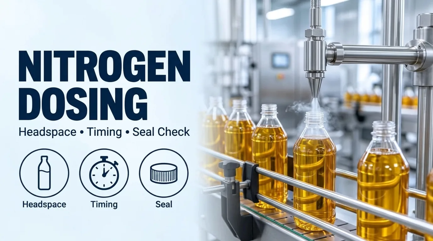
When we configure liquid filling lines and edible oil bottling lines, placing a cryogenic dosing station between the filler and the capper addresses both headspace oxidation and lightweight container collapse.
Our LINEVO Industrial Edible Oil Bottling Line integrates high-speed liquid filling, capping, and precision multi-side labeling into a continuous flow using a Siemens PLC control architecture, a Precision "Multi-Side" Labeling Engine, and servo-driven synchronous modules.
Our LINEVO Automatic Labeling Machine for Square Edible Oil Bottles is engineered for square PET or glass bottles (olive oil, vegetable oil, sesame oil, etc.) and uses high-pressure, multi-stage rolling modules so labels adhere firmly to plastic or glass, resisting oil-mist environments without peeling or bubbling.
According to Vacuum Barrier Corporation, over time the small amount of oxygen trapped in the headspace above packaged cooking oil is gradually absorbed by the product, causing pressure inside the bottle to decrease and creating a partial vacuum that can pull the sides of lightweight plastic bottles inward, resulting in paneling.
Vacuum Barrier Corporation's cooking oil application recommends adding approximately 2 to 3 PSI of pressure during capping to prevent future bottle paneling while maintaining package integrity.
According to Vacuum Barrier Corporation, nitrogen is an inert gas that will not react with cooking oils or alter their flavor, aroma, or quality, and it makes up roughly 78 percent of the Earth's atmosphere.
In a food science study on cold-pressed rapeseed and sunflower oils tested in accelerated storage at 63°C and long-term storage at 20°C (Acta Scientiarum Polonorum Technologia Alimentaria), after 20 days of the Schaal oven test at 63°C the peroxide value in the flushing with nitrogen rapeseed and sunflower oils was, respectively, 4 and 7 times lower than in the control samples (without nitrogen).
In the same study's long-term storage test (with access of light 20°C), the peroxide value of oil flushing with nitrogen after 6 months of storage was 2.3 to 2.8-fold lower, respectively, than in the control sample.
Chart Inc.'s documented extended shelf life studies show a 90-95% reduction in headspace oxygen content and a 59% reduction in total package oxygen when compared to a traditional gaseous nitrogen purge of headspace.
Chart Inc.'s documented nitrogen savings also show a 46% reduction in nitrogen spend when using Chart's liquid nitrogen dosing system compared to traditional gaseous nitrogen purging.
Cryogenic Phase Expansion, Fill-Height Consistency, and Shallow Headspace Splash Control
Controlling internal bottle pressure begins with the physical phase change of liquid nitrogen and the fill-level accuracy of the upstream liquid filler.
According to Vacuum Barrier Corporation, liquid nitrogen has a boiling temperature of -320°F (-196°C) and will rapidly boil away when exposed to room temperatures, so insulated equipment must be used to ensure efficiency and safety.
According to Vacuum Barrier Corporation, when boiling from liquid to gas, nitrogen expands roughly 700 times; safety relief valves (SRVs) are installed on tanks, piping, and dosers to prevent over-pressurization and potential equipment ruptures, and a safety relief valve must be placed between any two shut-off valves where nitrogen could be trapped.
According to the Chart Inc. CryoDoser manual, the normal oxygen content of air is approximately 21%, and when humans are exposed to an atmosphere containing only 8 to 12% oxygen, unconsciousness can be immediate with virtually no warning.
According to Vacuum Barrier Corporation, too small of a dose can lead to unstable containers, the possibility of collapse, or food spoilage in inerting processes, whereas if containers are dosed with too much nitrogen, there is a risk of containers bulging or bursting, which could cause jamming and downtime.
According to Vacuum Barrier Corporation, to reliably and accurately control the liquid nitrogen dose for each container up to speeds of 2000 bottles per minute and meet the production goals of pressurization, a doser relies on consistent fill heights from the filler, because even a small change in fill height can lead to under or over-pressurization.
In our edible oil filling configurations, oil left on the nozzle after shut-off runs down the neck and onto the bottle where a clean neck matters for the cap and label, while air carried in with the oil can foam in the bottle and a fast fill can splash, so filling from the bottom up or slowing near the end are the usual ways to limit foam and splash, used alongside nozzle shut-off, drip trays, and bottle spacing.
Vacuum Barrier Corporation's 3-D Technology (Directional Dose Dispersion) addresses shallow headspace in lightweight and hot-fill beverages to eliminate splash while accurately providing pressure, delivering discrete dosing at all line speeds to a target pressure of ± 1% psi even during extreme acceleration or deceleration.
Packaging Europe reports that Sidel's rPET-compatible Nitro Square bottle for nitrogen-dosed still water with liquid nitrogen dosing apparently reaches an hourly output of 2,600 bottles per mould on Sidel machinery, where its rigid sections and flexible pressure-absorbing surfaces work together to maintain the bottle's shape.
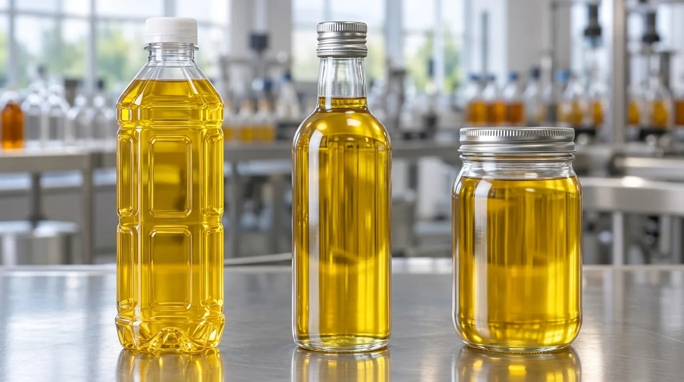
Compare Headspace Geometry Across Lightweight PET and Glass Edible Oil Containers
Station Spacing Between Filler and Capper: Inerting Travel Time vs Pressurization Capture
Where the dosing head sits along the conveyor between the filler discharge and the capper infeed depends on whether the primary engineering goal is headspace oxygen removal or internal container pressurization.
According to the Chart Inc. CryoDoser 2K manual, inerting is the process of removing oxygen (O2) from a container by dosing a relatively large amount of LN2 in the container so the liquid dose quickly converts into gas displacing air and oxygen, and the ideal location for the CryoDoser unit must allow for enough time between dosing and capping so that the liquid dose is converted into a gas.
According to the Chart Inc. CryoDoser 2K manual, pressurization occurs by dosing a relatively small amount of LN2 into a container where the liquid dose quickly converts into gas and the container is then capped or sealed to capture the expanding gas, so the CryoDoser unit should be installed as close to the capper as possible.
According to Vacuum Barrier Corporation, travel time from the doser to the seamer or capper should be minimized to prevent excess boiling or loss of nitrogen.
According to Vacuum Barrier Corporation, shaking or bouncing containers on the conveyors can force nitrogen and product out of the package before closure.
When space near the capper is limited, Chart Inc.'s Hot Chute nozzle handles narrow to wide mouth openings with discrete dosing up to 400 cpm and is recommended for discrete dosing with limited space near the capper.
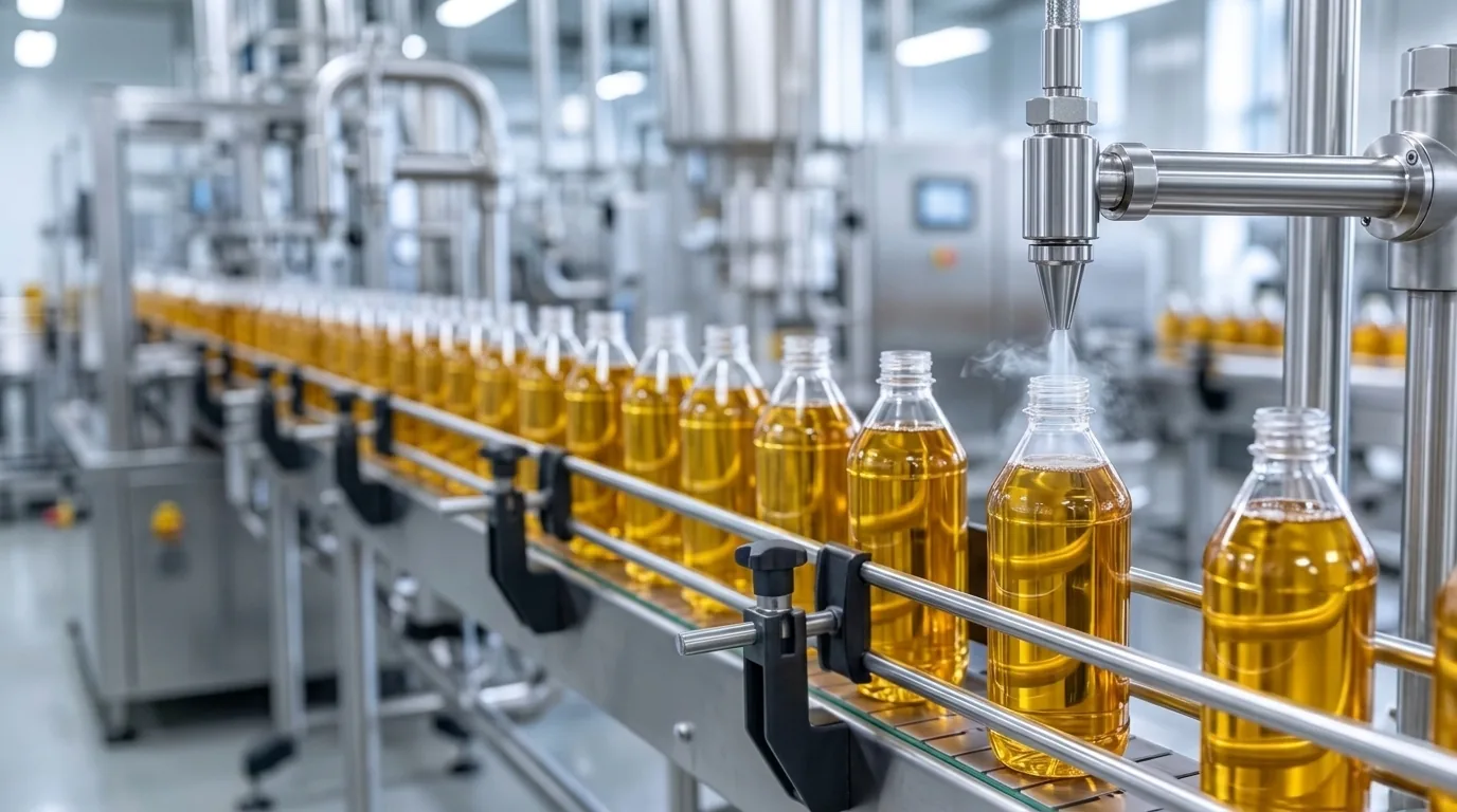
According to the Chart Inc. CryoDoser 2K manual, the dosing head should be directly over the container opening, is typically installed 1/2" - 3/4" above the container opening, and the CryoDoser unit must be manually adjusted to accommodate different sized containers running on the same production line.
According to the Chart Inc. CryoDoser 2K manual, three nozzles are supplied with the CryoDoser 2K system in 0.040 inch, 0.050 inch, and 0.060 inch sizes, and custom sizes may be ordered from Chart.
For support stand mounting, the Chart Inc. CryoDoser manual specifies measuring 32.5" (825mm) back from the dosing head location (the distance from the center of the support stand to the farthest point on the dosing head) and installing the four 5/8" bolts included with the support stand.
According to the Chart Inc. CryoDoser 2K manual, the CryoDoser unit has a self-regulating dosing head heater with a maximum temperature of 150°F (65°C) that prevents frost or ice formation at the dosing head area, and the dosing head heater has a built-in splash guard to minimize the dosing nozzle's exposure to splashed product or LN2.
Position the Cryogenic Dosing Nozzle Over Open-Neck Bottles Ahead of the Capper
Inerting vs Pressurization Setup and OEM Dosing System Specifications
Compare published OEM liquid nitrogen dosing configurations across operating speed, dose duration resolution, and repeatability.
| System or Mode | Line Speed and Operating Window | Dose Resolution and Minimum Duration | Published Accuracy or Head Pressure |
|---|---|---|---|
| Chart CryoDoser 2K Inerting Mode | Enough time between dosing and capping so the liquid dose is converted into a gas | Relatively large amount of LN2 dosed to displace air and oxygen (O2) | Dosing head typically installed 1/2" - 3/4" above container opening |
| Chart CryoDoser 2K Pressurization Mode | CryoDoser unit should be installed as close to the capper as possible | Relatively small amount of LN2 dosed and capped or sealed to capture expanding gas | 0.040 inch, 0.050 inch, and 0.060 inch nozzles supplied with CryoDoser 2K |
| Chart CryoDoser FleX (Pack Premier & Craft Custom) | Discrete dosing 1 to 2000 cpm (60 to 120,000 cph) or 30 to 750 cpm (1800 to 45,000 cph) | 0.1 ms (Pack Premier) and 1 ms (Craft Custom) resolution; 0.002 grams/dose minimum | ± 2% of dose repeatability; 0.34 psi (0.023 bar) head pressure; 33 lbs (15 kg) 316L stainless steel body |
| Chart Electric Dosing System (EDS) & Hot Chute | EDS discrete doses above 2000 containers per minute; Hot Chute discrete doses up to 400 cpm | EDS actuation speed of five milliseconds and dose duration resolution of 0.1 milliseconds | Hot Chute recommended for narrow to wide mouth openings with limited space near capper |
| Vacuum Barrier MiniDose G3 & Linerter III | MiniDose G3 up to 200 BPM (with single dose lab testing); Linerter III discrete dosing up to 500 CPM | MiniDose G3 minimum dose duration of 25ms; Linerter III minimum dose duration of 12ms | MiniDose G3 accurate to ± 5% dose weight (Siemens S7-1200 PLC, KTP 600 4" touchscreen); Linerter III ± 3% dose weight |
| Vacuum Barrier G3 Pro & NITRODOSE G3 Servodoser | G3 Pro discrete at 2000 BPM (continuous stream after); Servodoser at 2000 BPM without nozzle change | G3 Pro minimum dose duration of 6ms; Servodoser minimum dose duration of 5ms | G3 Pro accurate to ± 3% dose weight; Servodoser accurate to ± 1% dose weight |
Comparison of headspace inerting versus container pressurization placement rules and OEM liquid nitrogen dosing system specifications.
Speed Synchronization, Pocket Detection, and High-Speed Camera Distance Delay Calibration
At variable bottling speeds, the dosing controller must track container presence, pocket arrival, and conveyor velocity so each droplet lands cleanly inside the bottle neck.
According to the Chart Inc. CryoDoser 2K manual, Chart provides a PNP 18mm ultrasonic sensor with the CryoDoser 2K system where ideal sensor placement is about four to six pockets from the dosing head, and if the sensor does not detect a container for the user-defined number of seconds, the CryoDoser unit will stop dosing.
According to the Chart Inc. CryoDoser 2K manual, Chart provides a PNP 12mm inductive proximity sensor with the CryoDoser 2K system, and the SICK encoder provided by Chart comes from the factory preset to 500 pulses per container.
According to the Chart Inc. CryoDoser 2K manual, Pulses (container to container) is the pulse count between timing sensors, where a low number indicates a low resolution and a high number indicates the possibility of exceeding 20,000 pulses per second.
According to the Chart Inc. CryoDoser manual, for Distance Delay Calibration Point Low Distance Delay (mm), operators jog the filler until the timing sensor is activated (distribution block D-3 cable, yellow light) and measure the distance from the center of the dosing head to the leading edge of the container, which is ~75% of the 'Container CL to CL' value.
According to the Chart Inc. CryoDoser manual, for Distance Delay Calibration Point High Distance Delay (mm), operators enter 10% of the 'Container CL to CL' value as a starting point and verify with a high speed camera or similar, adjusting accordingly.
Post-Capping Torque Retention, Pressure Distribution, and Leak vs Doser-Valve Diagnostics
Once the bottle enters the capper, the closure must trap the expanding nitrogen gas and hold internal pressure through storage and distribution.
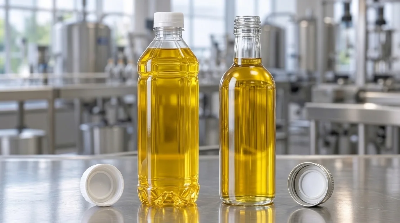
In our automatic capping machine line integration guide, ASTM D2063/D2063M-24 describes manual measurement of removal torque over time for matching continuous-thread packages under specified environmental conditions, and a leaking pack also needs the agreed leak check because a torque reading alone does not identify a damaged liner, contaminated sealing face, or mismatched neck.
According to ASTM D2063/D2063M-24 Clause 1.1, this test method is a quantitative method that measures removal torque of continuous thread closures on containers, with matching finishes for predetermined environmental conditions over time.
According to ASTM D2063/D2063M-24 Clauses 5.2 and 5.3, this test method can be used for the evaluation of container/continuous thread closure systems under controlled conditions (where the application torque is known and the applied downward force to the closure is zero), with the use of a non-automated, spring torque-meter (with either a dial indicator or a digital readout) or a torque wrench.
According to Antares Vision Group, as nitrogen vaporises to pressurise the headspace and rigidify the bottle, the process introduces two distinct failure modes that affect product quality and production efficiency: bottle leaks (N2 escaping through a defective seal), and doser malfunctions (one or more dosing valves applying too little or too much nitrogen).
According to Antares Vision Group, because every container is individually measured, an in-line inspection system can build a statistical profile of the pressure distribution across the production batch and correlate each reading with the specific capping head or dosing valve that handled that container, so if one doser valve is under-performing by applying too little N2, the system identifies it by cycle number and valve position.
In Chart Inc.'s MicroDose application findings, utilizing sensors to detect filling line speed, pocket detection, bottle presence, inputs independent of the filler, and electronic adjustments for fine tuning, 3.0 +/-1 psig internal bottle pressure is achieved at the 99% level (.5 L size), with sample size 1,000 findings showing 99% at 2 to 4 psi and 56% at 3 psi.
In Chart Inc.'s larger MicroDose sample size of 27,000 (.5 L size), findings showed 96.5% at 2 to 5 psi and 67% at 3 to 4 psi alongside the 1,000-bottle sample where 3.0 +/-1 psig internal bottle pressure is achieved at the 99% level.
Inspect Continuous-Thread Closures and Sealing Liners Alongside Filled Oil Bottles
Pre-RFQ Specification Checklist for a Liquid Nitrogen Dosing Bottling Line
Compile these container, headspace, and layout details alongside our line layout planning guide and filling line RFQ checklist before requesting a bottling line proposal.
- Vacuum Barrier Corporation's Bottle Requirements intake checklist specifies Portable Dewar (22psi), Production Rate (Bottles per Minute), Bottle Centerline Spacing, Bottle Opening (Inside Diameter), maximum pressure the bottle is able to withstand, Target Bottle Pressure (psig) at 25°C, maximum allowable oxygen in headspace, and Distance From Filler to Closing Machine.
- In our line layout engineering scope, utility drops (electrical power, compressed air, nitrogen or vacuum) to each station position are routed and terminated on site by your facility team.
Frequently Asked Questions
- 01How much internal pressure is recommended when dosing liquid nitrogen into cooking oil bottles before capping?
- Over time, the small amount of oxygen trapped in the headspace above packaged cooking oil is gradually absorbed by the product, causing internal bottle pressure to decrease and creating a partial vacuum that can pull lightweight plastic bottle walls inward (paneling). To prevent future bottle paneling while maintaining package integrity, Vacuum Barrier Corporation's cooking oil application recommends adding approximately 2 to 3 PSI of pressure during capping.
- 02Should the liquid nitrogen dosing head be mounted closer to the filler or closer to the capper?
- Mounting location depends on whether your goal is headspace inerting or container pressurization. According to the Chart Inc. CryoDoser 2K manual, inerting doses a relatively large amount of LN2 to displace air and oxygen (O2), so the CryoDoser unit location must allow for enough time between dosing and capping so that the liquid dose is converted into a gas. Pressurization doses a relatively small amount of LN2 and caps the container to capture the expanding gas, so the CryoDoser unit should be installed as close to the capper as possible.
- 03How are low-speed and high-speed distance delays calibrated on a liquid nitrogen dosing bottling line?
- On the Chart Inc. CryoDoser 2K system using a PNP 12mm inductive proximity timing sensor and a SICK encoder preset to 500 pulses per container, Low Distance Delay (mm) is determined by jogging the filler until the timing sensor (distribution block D-3 cable, yellow light) activates and measuring from the center of the dosing head to the leading edge of the container, which is ~75% of the 'Container CL to CL' value. High Distance Delay (mm) starts at 10% of the 'Container CL to CL' value and is verified with a high speed camera or similar.
- 04How do post-capping checks distinguish a leaking bottle cap from a malfunctioning nitrogen doser valve?
- According to Antares Vision Group, liquid-nitrogen dosing introduces two distinct failure modes: bottle leaks (N2 escaping through a defective seal) and doser malfunctions (one or more dosing valves applying too little or too much nitrogen). Antares Vision Group states that because every container is individually measured, its in-line system can build a statistical profile of the batch pressure distribution and correlate each reading with the specific capping head or dosing valve that handled that container, identifying an under-performing doser valve by cycle number and valve position.
[Request]
Send Your Bottle Drawing, Target Pressure, and Filler-to-Capper Layout
Share your bottle drawing, liquid product details, target shift output, and filler-to-capper spacing on WhatsApp so our engineering team can review the filling, nitrogen dosing integration, capping, and labeling layout.
Our team reviews your product, container and line requirements with you.
[Keep planning]
- Liquid Filling LinesFoam, drip or a narrow bottle opening can make the wrong filler a poor fit. Start with liquid behavior and container dimensions, then match the filling and downstream stations.
- Edible OilOil left on the neck after filling weakens the cap seal and the label. Start from the oil and the bottle format; the filler, capper and labeler follow.
- Line LayoutPlan filling line space around product movement, machine interfaces, operation and service access. The final layout should connect the selected equipment with actual site dimensions, utilities and the move-in route.
- RFQ ChecklistPrepare a filling line RFQ with the product, container and closure, required accepted output, site layout and delivery scope. A shared brief lets engineering define each station and its interfaces on the same basis.
- Capping Machine IntegrationPoor cap engagement wastes filled bottles. Match an automatic capping machine to the closure, bottle restraint and cap feed, then define torque checks and line interfaces before comparing output.