
[Buying guides]
Shrink Sleeve Labeling Machine and Steam Tunnel Line Guide
We size a shrink sleeve labeling machine and heat tunnel together so the film reel, mandrel, cutter head, tunnel zones, and conveyor buffers match the container profile and upstream filler handoff.
Updated November 2026
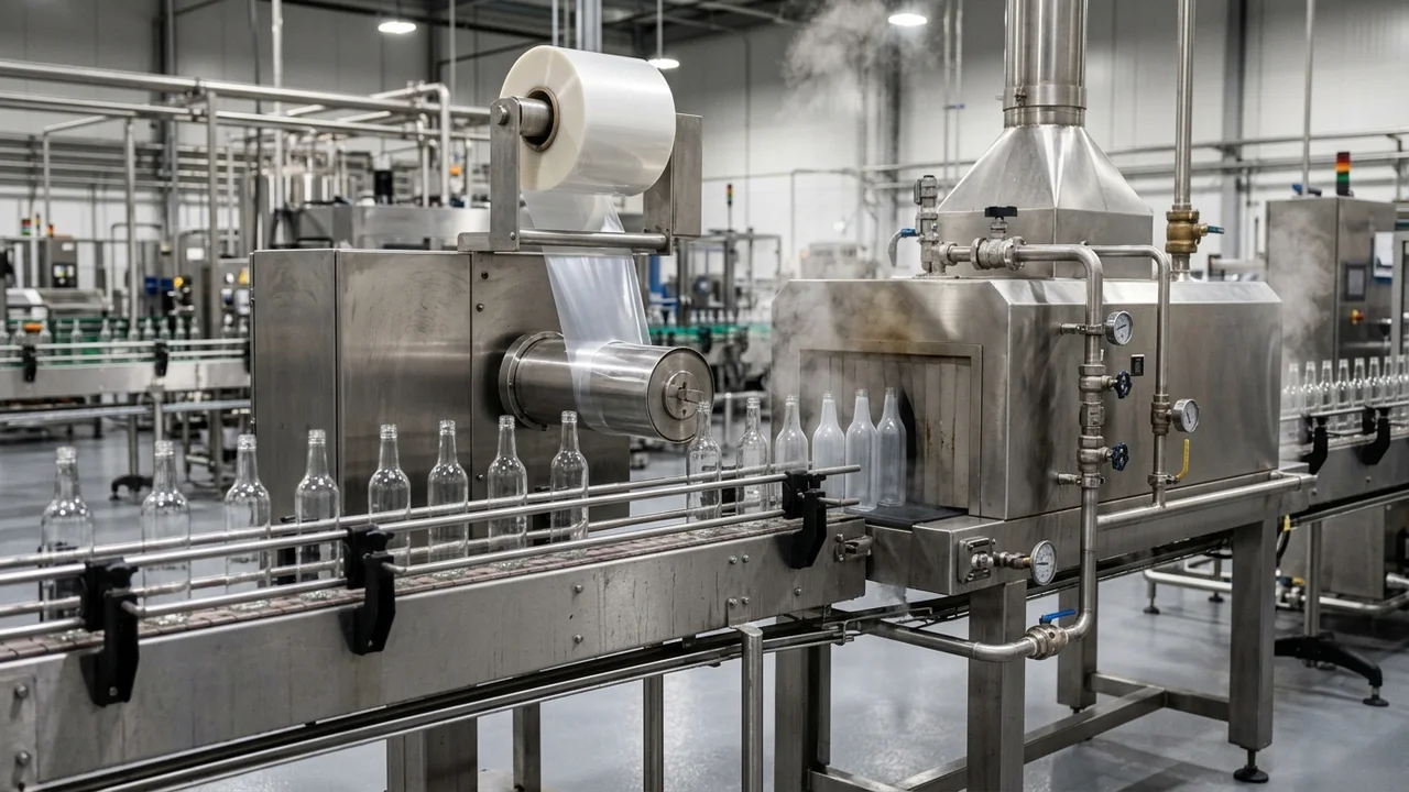
How a Shrink Sleeve Labeling Machine Applies and Shrinks Tubular Film
When we integrate a shrink sleeve labeling machine into a complete liquid filling line or review station boundaries across our packaging line buying guides, we treat the sleeve applicator and the heat tunnel as one synchronized subsystem. In our LINEVO labeling guidance, shrink sleeves follow a separate process from self-adhesive labeling by cutting from tubular film, placing over the container, and shrinking in a heat tunnel. On our LINEVO Industrial Shrink Sleeve Labeling Line, the system applies sleeves to beverage and liquid bottles and shrinks them in a heat tunnel. On our LINEVO Automatic Beverage Bottle Shrink Sleeve Labeling Machine, the system is engineered for automated shrink-sleeve application on mineral water, juices, energy drinks, and dairy products.
On our LINEVO Automatic Beverage Bottle Shrink Sleeve Labeling Machine, the line can be equipped with a Steam or Hot-Air Tunnel featuring digital temperature and airflow management so sleeves shrink evenly without bubbles, wrinkles, or distortions. On our LINEVO Automatic Beverage Bottle Shrink Sleeve Labeling Machine, configuration items for engineering review include servo-driven sleeve feeding and cutting modules, an Industrial PLC and Smart Diagnostic Suite, and a Siemens PLC and HMI interface. In Sleeve Technology's shrink sleeve guide, inside a shrink sleeve applicator flat film is fed from a continuous reel, opened over a mandrel (a shaped spear that expands the film into a tube), cut to the correct sleeve length using a rotary cutter, and pushed down over the product by transfer rollers.
After the sleeve drops over the bottle, pre-tacking, heat shrinking, drying, and inspection complete the station loop. In Sleeve Technology's shrink sleeve guide, some shrink sleeve lines include an intermediate tacking unit that uses hot-air nozzles to lightly pre-shrink a small portion of the sleeve in place so the sleeve does not shift on the conveyor before entering the shrink tunnel. In the same Sleeve Technology guide, in a steam-based shrink tunnel adjustable steam nozzles apply heat evenly around the container, followed after shrinking by a drying unit to remove residual moisture from the steam process and a camera inspection system to eject defective products. In Wolf Packing's shrink sleeve label guide, converters specify tight layflat tolerances of typically +/-0.5 mm for high-speed lines to prevent crooked opening or machine jams, and consistent cut lengths within +/-1 mm so sleeves maintain uniform appearance across production runs.
Inspect the Applicator Cabinet and Inline Shrink Tunnel Layout
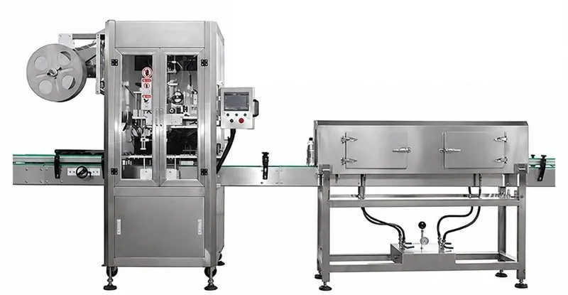
Applicator Speed Tiers and Machine Envelopes
Before selecting a shrink sleeve label applicator, we match container diameter, container height, film layflat width, film gauge, and changeover architecture against applicator families across low, mid, and high speed tiers. In Axon's SLX technical brochure, Axon SLX Series mandrel-style shrink sleeve applicators utilize dedicated servo drives for the feedscrew, film feed system, and cutting assembly for steady-state production speeds up to 800 containers per minute. In the same Axon SLX brochure, SLX applicators are designed for tool-less size changeovers that can typically be completed in less than 10 minutes using push-button height adjustment and recipe-driven parameter recall.
For mid-speed and specialty formats, blade-free perforation, wide-format mandrels, vacuum spreader guides, and step-by-step center pillar shooters provide distinct mechanical envelopes. In Axon's product portfolio, ZPT mid-speed shrink sleeve applicators use Zipper Perforation Technology to deliver cuts without traditional cutting blades at speeds up to 220 containers per minute. In the same Axon portfolio, the Aurora mid-speed mandrel-style applicator delivers speeds up to 400 cpm for multi-pack bands, tamper-evident bands, and shrink sleeve labeling applications. In Axon's wide-format portfolio, the Aurora Wide mid-speed sleeve applicator handles film widths up to 300 mm and delivers performance up to 200 cpm for full body sleeves and over-the-cap sleeves. In Frain's Axon EZ-130 technical listing, the 130 vacuum-style shrink sleeve applicator is offered in single and dual head configurations, and machine changeovers can be performed in as little as 5 minutes.
| Applicator Family | Container & Film Envelope | Speed & Mechanical Configuration |
|---|---|---|
| Axon Mandrel Series (SLX) | 30-125 mm (1.2-4.9 in.) container diameter; 50-200 mm (2.0-7.8 in.) layflat; 40-70 micron (1.5-3.0 mil) PVC, PETG, OPS, PLA (optional thin-gauge system) | Up to 600 cpm (SLX-600) or 800 cpm (SLX-800); dedicated servo feedscrew, film feed, and cutter; <10 min tool-less changeover |
| Axon Vacuum Series (EZ-100) | 11-68 mm (0.43-2.68 in.) product diameter; 20-112 mm sleeve layflat; ~40-70 micron PVC, PETG, OPS, PLA | Up to 150 cpm (single head) or 300 cpm (dual head); vacuum spreader guides; two-blade cutter; <=5 min tool-less changeover |
| Axon Neck Bander (EZ-130HS) | Containers up to 12 in. tall; film layflat widths up to 130 mm; film gauges up to 70 microns | Up to 150 cpm tamper-evident neck banding and sleeve application; <=5 min changeover on EZ-130 series |
| PDC Marburg & Deitz Banders | Pharmafill NB1: straight-sided or shoulderless bottles up to 9 in. high with BCV2 hugger belt conveyor | Up to 100 bpm; Marburg 625 FB on a 16-ft stainless conveyor paired with a 3-zone PDC KSA-70 steam tunnel |
| MIC Center-Pillar Shooter | 40-70 mm container diameter cutter plane; 100 mm reference label length | 150 BPM step-by-step center-pillar shoot structure; servo cutter head with <=1 mm cut precision |
Machine envelopes across shrink sleeve label applicators and neck banders
Shrink Sleeve Film Substrates: PVC, PETG, OPS, PLA, and Polyolefin
In PDC International's shrink tunnel brochure, standard shrink sleeve materials shrink up to about 55% in the transverse (horizontal) direction and high-shrink materials shrink up to about 70% in the transverse direction. In the same PDC International brochure, shrink sleeve films also have machine direction (MD) shrinkage of typically 3 to 7%, which can cause sleeves to shorten in height and must be controlled. In BestPack's shrink film technical sheet, ASTM D2732 is the ASTM test method used to measure unrestrained thermal shrinkage percentage of shrink film (such as 60 at 260 degrees F).
In Wolf Packing's shrink film guide, PVC initiates shrinking at 122 to 140 degrees F with a max shrink ratio of 64%, whereas PETG starts higher at 158 to 176 degrees F with a max shrink ratio of 78%, OPS offers up to 75% shrink ratio, and PLA reaches 72%. In Wolf Packing's shrink sleeve label guide, PVC shrinks at 60 to 80°C (with some applications running up to 100 to 113°C), PETG operates at 140 to 180°C (284 to 356°F) and achieves shrink rates up to 78%, and PLA achieves greater than 70% shrink at 80 to 100°C in the tunnel. In Packaging Strategies' Eastman Embrace report, Eastman Embrace LV copolyester is a one-resin shrink film designed for thin-walled containers that provides a lower shrink force. In Packaging Europe's ALPLA and CCL Label report, the EcoFloat shrink sleeve is made from low-density polyolefin so that it separates from PET flakes during the recycling process, and is applied after the 0.33L bottle is filled.
| Film Substrate | Fahrenheit Initiation & Max TD Shrink | Celsius Tunnel Window & Application Behavior |
|---|---|---|
| PVC & PETG | PVC: 122-140°F initiation, 64% max shrink; PETG: 158-176°F initiation, up to 78% max shrink | PVC: 60-80°C (up to 100-113°C); PETG: 140-180°C (284-356°F) for steep neck-to-body contours |
| OPS & PLA | OPS: up to 75% max shrink ratio; PLA: up to 72% max shrink ratio | PLA: >70% shrink at 80-100°C tunnel window; typical film MD vertical shrinkage of 3-7% |
| Low-Force Copolyester | Controlled transverse shrink profile for lightweight or thin-walled containers | Eastman Embrace LV single-resin copolyester engineered with reduced shrink force to prevent sidewall squeeze |
| Floatable Polyolefin | Low-density polyolefin sleeve structure matched to PET bottle recycling streams | EcoFloat sleeve separates by density flotation from PET flakes during wash-plant recycling (applied post-fill on 0.33 L bottles) |
Shrink sleeve film shrink ratios, initiation temperatures, and specialty resin behavior
Steam Shrink Tunnel vs Electric Hot-Air and Infrared Tunnels
Choosing between a steam shrink tunnel and an electric hot-air or radiant infrared shrink tunnel depends on heat transfer mechanism, container thermal stability, moisture sensitivity, and plant steam utilities. In Racklify's shrink tunnel comparison, steam tunnels transfer heat primarily by condensation where latent heat is released during condensation to shorten dwell time, whereas hot-air tunnels use convective heating via forced air where steam utilities are unavailable. In PDC International's shrink tunnel brochure, because steam systems provide more uniform heat impingement than air systems, steam tunnels provide more precise label registration and shape conformance, and are also used with containers under pressure or when low flash point or flammability is a factor.
Operating temperature ranges and conveyor construction differ sharply between steam and dry heat tunnels. In PDC International's heat tunnels guide, steam shrink tunnels are used on empty bottles to avoid deformation because they operate at lower temperatures (180 to 200 degrees F) than dry heat shrink tunnels (350 to 500 degrees F). In PDC Europe's shrink sleeving guide, hot air tunnels are used for neckbanding tamper evidence and shrink sealing full body sleeves on small containers where conveyors and wear strips must withstand 200 degrees F in the tunnel to 600 degrees F, while conveyors passing through steam tunnels must be constructed to operate with moisture and condensate. In Karlville's shrink tunnel comparison, hot-air shrink tunnels operate at moderate shrinkage temperatures (80 to 200°C) for products sensitive to moisture, while the Karlville Tornado hot-air tunnel uses a preheat temperature of 80 to 90°C and reduces exposure to very high heat to less than a second.
Multi-zone tunnel length, aperture dimensions, electrical ratings, and steam filtration scale with sleeve height and line cadence. In PDC International's shrink tunnel brochure, Single Zone Tunnels available in either Hot Air or Radiant configurations have a 9, 12 or 18 kW power range and 26, 36 or 46 inches length range, while Dual Zone Tunnels have an 18 or 24 kW power range and 52 or 72 inches length range. In the same PDC brochure, Single Zone Tunnels for tamper-evident bands have a 40 inches length range, a 4 to 8 inches opening height range, and a 5 to 7 inches opening width range. In PDC International's shrink tunnel brochure, Dual Zone Tunnels for shrink labels have an 80 inches length range consisting of 2 40-inch zones, a 12 to 14 inches opening height range, and a 7 to 11 inches opening width range. In PDC International's brochure, tunnels are built of 18 and 20 gauge stainless steel for 208/240 or 480 VAC 3-phase power. In the same brochure, hot-air or radiant tunnel temperatures range from 200 degrees F in the tunnel to 600 degrees F at the elements. In the same brochure, steam filters clean steam to 0.1 micron to produce culinary-grade steam.
Both plant-steam and self-contained steam generator tunnels, alongside convective and hybrid IR-plus-steam tunnels, have distinct chamber sizes, pressures, and steam consumption rates. In Sleeve Technology's steam tunnel specifications, each section contains two adjustable nozzles and operating pressure typically runs between 3.5 and 4.0 bar, with a hard safety maximum of 8 bar. In Packaging Strategies' PDC steam boiler report, the PDC KST 55-712 single-zone steam shrink tunnel with an integrated compact steam boiler has 5 rows of steam distribution tubes per side for a total of 10 steam runs, a 7 inches width by 12 inches height opening, and shrinks PVC, PETG, OPS, and PLA films down to 30 microns at up to 100 containers per minute. In Frain's PDC KST80-712 technical listing, the KST80-712, 304 stainless steel dual-zone steam shrink tunnel and conveyor with self-contained 30 kW steam generators has a total aperture 7 inches wide, 2 48-inch drip trays, and manifold adjustable flow controls. In Axon's HE-500 technical brochure, the HE-500 steam shrink tunnel features an Integrated Steam Generation System requiring no plant boiler, 16 adjustable perforated steam bars, and accommodates container or multipack diameters up to 5 inches and heights up to 9.5 inches. In Axon's ThermoPoint technical brochure, ThermoPoint plant-steam shrink tunnels feature 3 independently controlled steam zones (each with its own adjustable rate, height, and angle) and accommodate containers or multipacks up to 6 inches wide and 15 inches tall. In Axon's ThermoFlow technical brochure, the ThermoFlow standalone steam shrink tunnel integrates a built-in low-pressure steam generator that is not subject to the regulatory requirements of high-pressure boiler systems, supports container diameters up to 6 inches and heights up to 12 inches, and offers an optional third steam zone. In Axon's EZ-SRB technical brochure, EZ-SRB convective heat shrink tunnels are available in 24 inches and 36 inches modular zones using digitally controlled recirculating forced-air heating without steam or water connections, supporting containers up to 6 inches in diameter and up to 10 inches tall.
Additional regional and industrial tunnel models illustrate how steam inlet pressure, electric blower power, and generator kW pair together. In SIGMA Equipment's Axon EZ-80 technical listing, the Axon EZ-80 Steam Sealer has a 6.5 inches W by up to 12.5 inches H by 72 inches L chamber, runs at 50 psi steam inlet and 2.2 psi steam outlet with dual electric IR pre-shrink, and operates on 220 volts, 50/60 hertz, 1 phase, 6 amps. In Frain's American Film & Machinery technical listing, the WSN-300-2M stainless steel steam shrink tunnel has an 8 inches high by 79 inches long total aperture, a maximum operating temperature of 212 degrees F at 43 to 57 psi (3 kg/cm2), and a steam consumption rate of 200 litres (52 gallons) per hour. In Alfpack's DZBS-1135 steam shrink tunnel specifications, the DZBS-1135 tunnel has a 150 W blower and a 1000 x 110 x 350 mm tunnel chamber for a maximum packing size of 80 mm diameter by 300 mm height, paired with an LDR18-0.4-Z 9/18 kW steam generator supplying 24 kg/h of steam at 0.4 MPa. In Alfpack's BSS-1538D electric shrink tunnel specifications, the BSS-1538D machine draws 8 kW power, handles a maximum packing size of 160 mm diameter by 350 mm height inside an 800 x 200 x 400 mm shrink tunnel chamber, and runs at 0 to 10 m/min conveyor speed on a Teflon net belt. In MIC Machinery's steam tunnel specifications, the steam shrink tunnel has a 0.75 kW blower, working pressure <=0.1 MPa, 20 to 30 kg/h steam consumption, and 0 to 35 m/min transporting speed, paired with a 24 kW steam generator producing 24 kg/h of vapor at 0.25 to 0.4 MPa.
| Aspect | Steam Shrink Tunnel | Electric Hot-Air / Radiant Tunnel |
|---|---|---|
| Heat Transfer & Temperature | Latent-heat steam condensation at 180-200°F (up to 212°F); short dwell time protects empty thin-wall bottles from distortion. | Forced convective air or radiant IR at 350-500°F (200-600°F at elements; 80-200°C in moderate-heat or <1 s high-heat zones). |
| Zones & Utility Loads | 1 to 3 steam zones; 3.5-4.0 bar (8 bar max) or 43-57 psi inlet; 20-30 kg/h (or 200 L/h) steam; 9-30 kW integrated boiler or plant steam with 0.1 micron culinary filter. | Single zone (26-46 in., 9-18 kW) or dual zone (52-80 in., 18-24 kW) on 208/240/480 VAC 3-phase power; no boiler, water, or drain piping required. |
| Target Packages & Conveyors | 360° contoured full-body sleeves, pressurized cans/aerosols, and low-flash-point products; requires condensate drip trays, exhaust hood, and post-tunnel air-knife dryer. | Tamper-evident neck bands, moisture-sensitive dry packages, and small rigid containers; requires high-temp conveyor wear strips rated for 200-600°F. |
Review Conveyor Indexing, Manifold Piping, and Exhaust Hoods Together
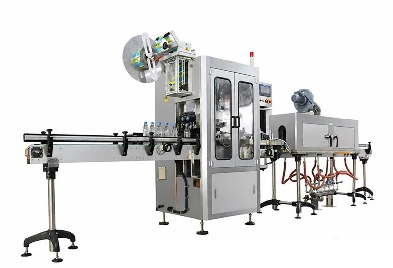
Where the Shrink Sleeve Station Fits on a Bottling Line
When we lay out a complete bottling line, the position of the shrink sleeve label applicator and heat tunnel relative to the filler, automatic capping machine, hot-fill or cold-fill process, and packaging line layout governs container stability and accumulation buffering. We apply the same station handoff checks across sauce and condiment filling lines and shampoo and lotion filling lines. In our LINEVO packaging-line planning documentation, line integration boundaries include transfer heights, directions and product orientation between units, run, stop, full, empty and reject signals exchanged between machines, and power, compressed air, vacuum or nitrogen supply utilities.
Filling before or after shrink-sleeve labeling changes both container rigidity and surface preparation before the applicator. In PDC Europe's shrink sleeving guide, empty plastic bottles and other containers deform at certain temperatures during shrinking, requiring testing in advance and very precise temperature controls, whereas full containers are much less likely to deform. In the same PDC Europe guide, when containers are labeled after being filled, bottles must be free of product and clean when labeled, and in the case of condensation air knives may be required to dry the bottles before labeling.
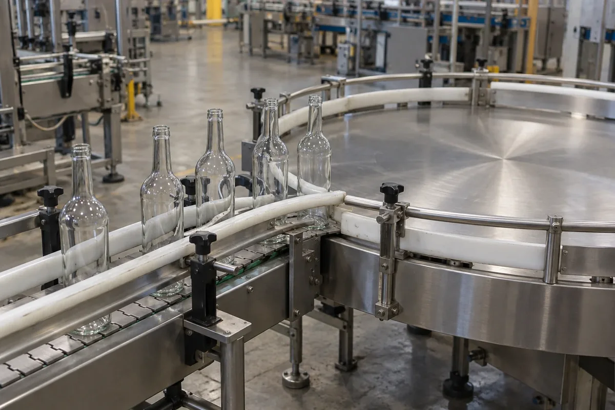
Inside the conveyor transfer and accumulation zones, bottle spacing and stop-recovery buffers follow deterministic line formulas. In our bottle labeling equipment line interface guide, for steady single-file bottle flow without slip, center pitch p = v / q (where conveyor speed v is in m/min and arrival rate q is in bottles/min) and clear gap g = p - d (where d is the bottle dimension along travel in metres). In the same bottle labeling interface guide, for constant arrivals during a downstream stop, buffer positions = incoming bottles/min x interruption seconds / 60, and recovery minutes = queued bottles / (downstream bottles/min - incoming bottles/min).
Buffer the Applicator Infeed Against Downstream Stops
Tamper-Evident Neck Bands, Zone Controls, and Defect Prevention
Whether a shrink sleeve labeling machine applies a dedicated tamper-evident neck band or a full-body sleeve that extends over the closure, perforation placement and neck-cap venting must be specified upfront. In PDC Europe's shrink sleeving guide, for tamper evidence shrink sleeves can be extended up over the cap of a container and perforated where the cap meets the neck, creating a tamper-evident seal that is visible at the point of purchase unlike inner seals. In Packaging Strategies' PDC perforation report, PDC International's perforation system for precision venting the junction of bottle-necks and caps allows evaporation of moisture and prevents cap corrosion, operating at speeds up to 400 bpm with sleeve diameter capacity between 1.5 and 7 inches.
In PDC International's heat tunnels guide, dual-zone shrink tunnels have two heating chambers and two thermostatically controlled zones in one shell so operators set dissimilar temperatures and the label at the base of the container is shrunk first, then the body, and finishing at the shoulder and neck. In PDC International's shrink tunnel brochure, Electronic Steam Control uses digital controllers with thermocouples and special linear valves so the tunnels self-monitor their temperatures and react to compensate for the thermal loads of full and cold products. In the same PDC brochure, Pre-Shrink Systems maintain control of the sleeve during the initial phase of shrinking and Post-Shrink Systems finish critical areas at the end of the process after the shrink tunnels, while airflow is paused when the machine is waiting for product. In PDC International's shrink tunnel brochure, a Power/Auto Lift Tunnel Stand provides motorized raising and lowering of the shrink tunnel and automatic raising if the conveyor stops.
| Control Subsystem | Engineering Function | Operational Verification |
|---|---|---|
| Dual-Zone Sequencing | Two thermostatically independent heating chambers inside one tunnel shell set to stepped temperatures. | Base of the bottle shrinks first, followed by the main body, and finishing at the upper shoulder and neck. |
| Thermal Load Compensation | Digital thermocouple controllers and linear steam valves modulate output for cold, filled containers. | Advance shrink trials verify temperature windows so empty plastic containers do not deform. |
| Pre-Shrink & Auto-Lift | Hot-air pre-shrink tacks the sleeve in place; post-shrink finishes critical contours; airflow pauses on line standby. | Motorized Power/Auto Lift tunnel stand automatically raises the heated hood if the bottle conveyor stops. |
| Cap-Neck Venting & Inspection | Precision micro-perforation vents trapped moisture at the cap-neck junction (1.5-7 in. diameter, up to 400 bpm). | Prevents closure corrosion under over-the-cap tamper bands; followed by post-steam drying and camera reject. |
Shrink sleeve process control hardware and defect prevention mechanisms
Shrink Sleeve and Tunnel Line Specification Worksheet
Before sending container drawings for a shrink sleeve station or a complete bottling line, pair this worksheet with our filling line RFQ checklist so every container dimension, film roll rule, and plant utility interface is captured upfront.
- Container geometry drawings showing narrowest neck finish, widest body diameter, vertical height, wall resin, and whether bottles enter filled or empty.
- Printed sleeve roll sample, solvent seam specification, layflat width, cut length, and perforation tear or cap-neck venting orientation.
- Selected shrink film resin, roll film gauge, transverse and longitudinal shrink behavior, and Thin Gauge Film Handling needs.
- Target bottles per minute alongside single-file conveyor center pitch, clear gap, and buffer positions for downstream stops.
- Tunnel heating medium selection between plant steam, self-contained boiler steam, or dry convective hot-air and radiant infrared zones.
- Downstream conveyor space reserved for pre-labeling condensation blow-off, post-steam drying units, and camera inspection rejection.
Sources
- LINEVO PACK: Automatic Beverage Bottle Shrink Sleeve Labeling Machine and Industrial Shrink Sleeve Labeling Line product technical sheets, linevopack.com.
- LINEVO PACK: Labeling Equipment and Packaging-Line Integration Solutions documentation, linevopack.com.
- Our LINEVO Engineering Library: Bottle Labeling Equipment Line Interface Guide, fillingline.net.
- Axon by ProMach: SLX, EZ, HE, ThermoPoint, ThermoFlow, and Convective Shrink Tunnel technical brochures.
- PDC International and PDC Europe: Shrink Tunnel Brochures, Heat Tunnels Guide, and Shrink Sleeving technical notes.
- Karlville, Racklify, and Sleeve Technology: Steam vs Hot-Air Shrink Tunnel and Applicator engineering guides.
- Wolf Packing, MIC Machinery, and Alfpack: Shrink Sleeve Film and Steam or Electric Shrink Tunnel technical sheets.
- Packaging Strategies, Packaging Digest, Packaging Europe, BestPack, Frain, and Sigma Packaging: Shrink Sleeve Line technical reports.
[Sources]
- LINEVO Automatic Beverage Bottle Shrink Sleeve Labeling Machine and Steam Shrink Tunnel product technical sheet. linevopack.com/products/automatic-beverage-bottle-shrink-sleeve-labeling-machine-with-steam-shrink-tunnel
- LINEVO Industrial Shrink Sleeve Labeling Line for Bottles and Cans product technical sheet. linevopack.com/products/industrial-shrink-sleeve-labeling-line
- LINEVO labeling equipment and shrink sleeve film configuration notes. linevopack.com/machines/labeling
- LINEVO packaging-line integration boundaries, transfer signals, and utility planning. linevopack.com/solutions
Frequently Asked Questions
- 01When should a bottling line use a steam shrink tunnel instead of an electric hot-air tunnel?
- Use a steam shrink tunnel when running 360-degree contoured full-body sleeves, empty thin-walled plastic bottles, pressurized containers, or low-flash-point products. Steam transfers latent heat by condensation at 180-200°F (versus 350-500°F in dry hot-air tunnels), providing uniform radial heat and shorter dwell times, whereas electric hot-air tunnels suit moisture-sensitive products, tamper-evident neck bands, and plants without steam utilities.
- 02What shrink ratios and temperature windows apply to PVC, PETG, OPS, and PLA shrink sleeve films?
- PVC initiates shrinking at 122-140°F (60-80°C tunnel window, up to 100-113°C) with a 64% maximum transverse shrink ratio. PETG initiates at 158-176°F (140-180°C / 284-356°F operating window) and reaches up to 78% shrink for deep container contours. OPS provides up to 75% shrink, and PLA achieves 72% maximum shrink (>70% at 80-100°C), while all sleeve films exhibit 3-7% machine-direction (vertical) shrinkage that must be accounted for in cut length.
- 03Should shrink sleeves be applied before or after filling plastic bottles?
- Applying sleeves after filling is generally safer for thin-walled plastic containers because the liquid mass absorbs heat and resists thermal deformation, provided the exterior bottle surface is washed clean of spills and dried with air knives if cold-fill condensation is present. Empty plastic bottles can be sleeved before filling when using low-temperature steam tunnels (180-200°F) and validated temperature controls.
- 04How do operators prevent sleeve shifting and bottom-to-top distortion inside the shrink tunnel?
- Lines prevent conveyor slip before the tunnel by using an intermediate hot-air tacking nozzle (pre-shrink unit) to lock the base or waist of the cut sleeve onto the bottle. Inside a dual-zone tunnel, two independently controlled chambers sequence heat from the bottom up - shrinking the container base first, then the main body, and finally the shoulder and neck so graphics do not pucker or trap air.
- 05What sleeve and line inputs should we send before requesting a shrink sleeve line quotation?
- Send your container neck and body drawings, empty-versus-filled arrival state, printed tubular film specimen (layflat width with +/-0.5 mm tolerance, cut length with +/-1 mm tolerance, film resin, and micron gauge), steam versus electric tunnel preference, transfer heights, inter-machine run/stop/reject signal logic, and available electrical, air, and steam utilities.
[Request]
Share Your Bottle Drawings, Film Gauge, and Steam Utilities
Send your container neck and body drawings, sleeve format, film resin, and available plant utilities through WhatsApp to review applicator and tunnel sizing for your bottling line.
Our team reviews your product, container and line requirements with you.
[Keep planning]
- Liquid Filling LinesFoam, drip or a narrow bottle opening can make the wrong filler a poor fit. Start with liquid behavior and container dimensions, then match the filling and downstream stations.
- SaucesParticles that do not suit the bottle opening can block filling or leave sauce on the sealing rim. Match the sauce at filling temperature, its pieces and the container opening before choosing stations.
- ShampooFoam in the neck can cause short fills and a messy bottle. Define the shampoo’s filling condition, bottle opening and closure before selecting filling and capping stations.
- Line LayoutPlan filling line space around product movement, machine interfaces, operation and service access. The final layout should connect the selected equipment with actual site dimensions, utilities and the move-in route.
- Buying GuidesGuides for each stage of a filling line purchase, from budget and selection to the information a proposal needs.
- RFQ ChecklistPrepare a filling line RFQ with the product, container and closure, required accepted output, site layout and delivery scope. A shared brief lets engineering define each station and its interfaces on the same basis.
- Capping Machine IntegrationPoor cap engagement wastes filled bottles. Match an automatic capping machine to the closure, bottle restraint and cap feed, then define torque checks and line interfaces before comparing output.
- Bottle Labeling Line InterfaceHand loading a bottle labeler can add downtime to a continuous filling line. Match your bottle labeling machine to bottle holding, label format and conveyor interfaces before comparing speed.
- Hot Fill vs Cold FillHot fill needs a package that tolerates heat and the pressure change during cooling. Cold fill needs a defined preservation and storage route. Compare the bottle, cap seal and connected stations before choosing the line.