
[Buying guides]
Paste Filling Machine Parts: Identify Before Ordering
Identify paste filling machine parts by the machine record, the component function and the product path. Separate wear seals from valve hardware and format parts, then check the drawing and material before ordering a replacement.
Updated October 2026
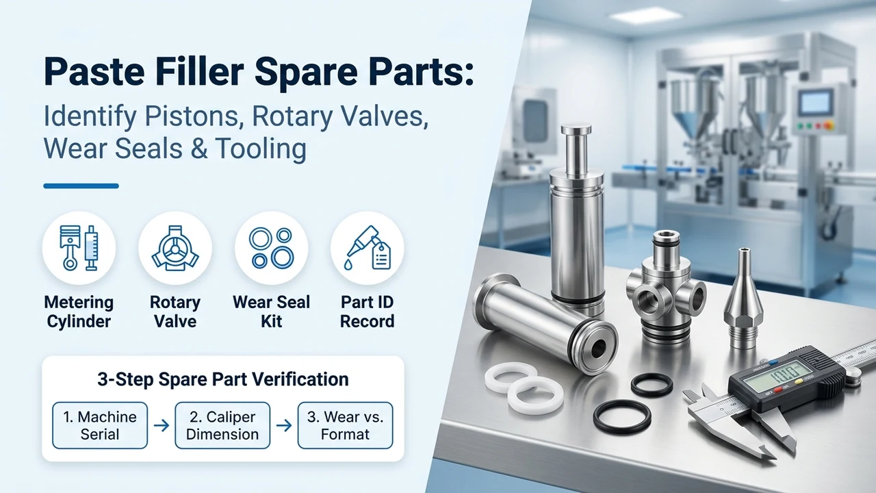
Quick View: Five Checks Before Ordering a Replacement Part
Scroll across to read all three columns.
| Check item | Record from your station | Why visual matching fails |
|---|---|---|
| 1. Machine identity | Nameplate photo with model, serial number and configuration revision | Two piston fillers from the same series can use different cylinder bores or valve bodies |
| 2. Product-path zone | Hopper, product cylinder and piston, directional valve, nozzle, or seal kit | Check piston seals, valves and product supply alongside the nozzle when locating a leak or short fill. |
| 3. Wear vs format role | Whether the part wore out in normal service or is being swapped for a new bottle or recipe | A degraded seal calls for a matching replacement; a new neck or dose window calls for a configuration check. |
| 4. Two-view geometry | Photos of the part installed in place and removed beside a scale, plus port or clamp type | Tri-clamp ferrules, NPT threads and piston seal grooves look alike in unscaled photos |
| 5. Contact conditions | Paste behavior, particulates, filling temperature in °C, and cleaning agents | Seal kits with identical dimensions are stocked in different elastomers such as Viton, EPDM or Silicone |
Why Visual Matching Fails on Paste and Piston Fillers
Identify a replacement part from the machine build record and its assembly drawing. Match the nameplate, model, serial number and revision to the part number or drawing callout, then check the installed orientation, connections and material. LINEVO’s spare-parts guidance uses these identifiers and scaled photographs to review compatibility.
Trace the component’s function through the product path: supply, metering cylinder, valve, transfer connections and nozzle. Separate a degraded wear item from tooling needed for a different dose or container. For a new viscous-product line, the paste filling lines page covers the wider configuration.
Use the original equipment manual and qualified service personnel for isolation, safe removal and replacement. Confirm the part identity and contact-material suitability against the unit’s serial record before ordering.
Trace Paste Filling Machine Parts Along the Product Path
Trace the paste from supply to the container mouth, identifying the metering and cutoff functions along the way. Keep product-contact components separate from the pneumatic or servo drive that moves them.
In the supply zone, product sits in a conical or rectangular hopper, or in a U-shaped stirring hopper when sauces contain suspended particles that would otherwise settle. On the intake stroke, a pneumatic air cylinder or servo drive retracts the product piston inside a sanitary stainless-steel metering cylinder, drawing paste through a directional valve. On the discharge stroke, the valve shifts and the piston pushes the measured volume through the transfer plumbing and out of the dispensing nozzle into the waiting bottle or jar. Depending on the machine, mechanical stops or servo position settings define the stroke; reed switches detect piston positions for the control sequence. Use the build-specific drawing to identify the adjustment.
If your station uses a rotary gear head rather than a reciprocating cylinder, use our piston filler vs gear pump filler difference guide to separate pump-head components from piston-path parts.
Cylinder and Seal Identification
Use the drawing to compare the cylinder, piston, seal grooves and mating surfaces. A used elastomer can change size and should not be the sole dimensional reference.
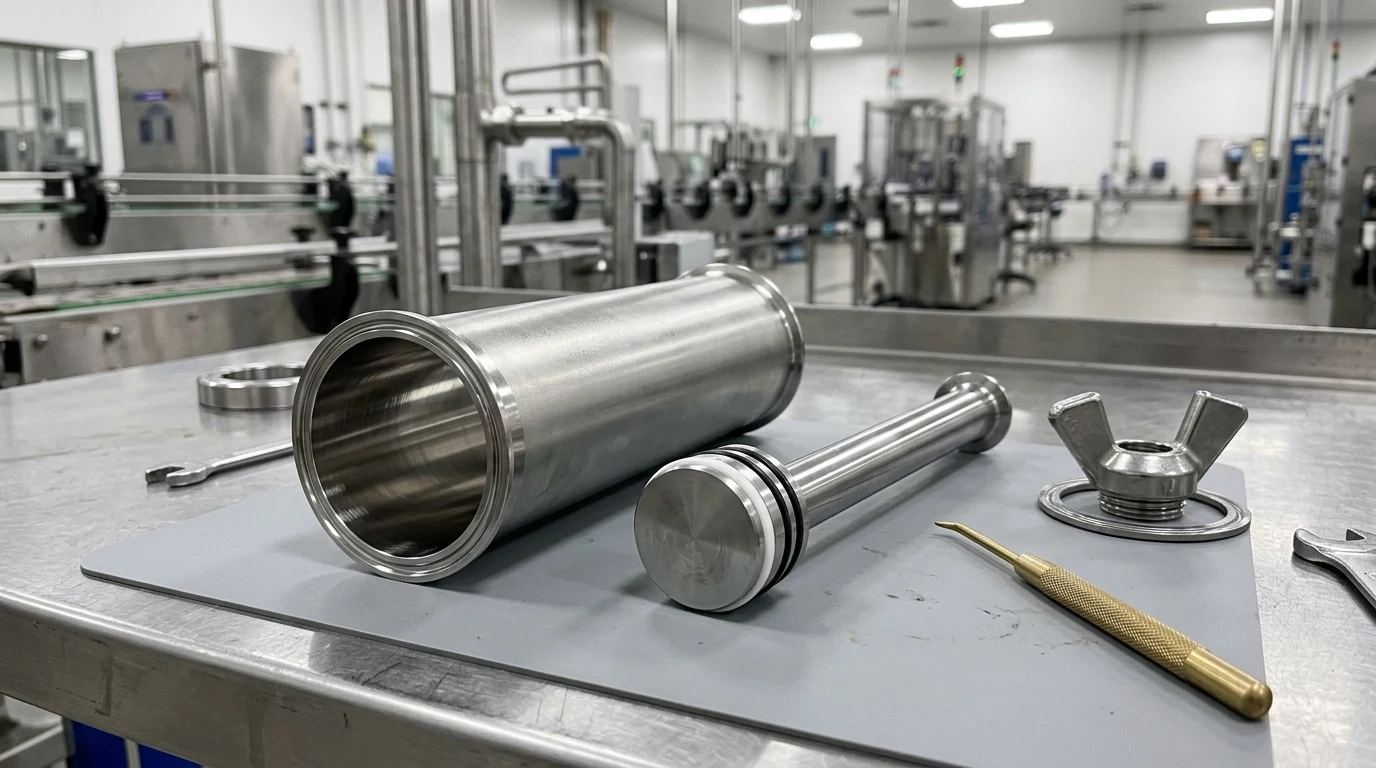
Product-Path Component Map: From Hopper to Nozzle Tip
Locate each installed assembly on the product-path drawing. Match its connection, dimensions and material to the machine record; the component arrangements below describe items to identify on the selected equipment.
| Station zone | Core assemblies and sub-parts | What changes the part specification | What to record from the unit |
|---|---|---|---|
| 1. Product supply and hopper | Conical or rectangular tank, U-shaped stirring hopper, agitator paddles and shaft seals, optional heating jacket and temperature probe, tank-lid protective trim or gasket. | Whether the paste settles, requires agitation for particulates, or needs temperature control to flow. | Hopper style, outlet connection type, agitator drive mount, and probe fitting thread or clamp size. |
| 2. Metering cylinder and piston | Sanitary product cylinder barrel, piston head, piston shaft, dynamic wiper ring or piston cup, static barrel O-rings, pneumatic drive cylinder, stroke-position sensor or servo actuator. | Target dose volume range (public catalogs index separate cylinder assemblies across distinct milliliter or ounce ranges) and drive method. | Cylinder model code, inner bore and stroke range from the manual, reed-switch or sensor marking, and piston seal groove layout. |
| 3. Directional or check valve | One-way check valve, three-way rotary valve, or chunky-product butterfly valve; valve spool or rotor; valve housing; actuator and mounting bracket; port tri-clamp gaskets. | Paste viscosity and whether seeds, pieces, or fibers must pass without jamming or shearing. | Valve body type, port outer diameter across the tri-clamp ferrule, actuator model, and internal rotor or seat configuration. |
| 4. Transfer plumbing and manifolds | Sanitary stainless-steel elbows, product transfer connector sleeves, flexible hoses, tri-clamp ferrules, heavy-duty wing-nut clamps, and flow-restrictor or full-port gaskets. | Line pressure, routing between the valve and fill head, and whether quick-release clamps are used for manual washdown. | Tubing and ferrule outside diameters, hose material marking, and whether gaskets are standard open bore or orifice restrictor style. |
| 5. Dispensing nozzle assembly | Fill-head body, interchangeable nozzle tip, positive shut-off plunger or stem, extended bottom-up tube, honeycomb anti-drip insert, diving-head cylinder or servo carrier. | Container neck inner diameter, whether the paste strings or foams, and whether top-fill or bottom-up diving motion is used. | Nozzle outer diameter relative to the bottle neck, shut-off mechanism type (pneumatic stem, spring check, or honeycomb screen), and tip thread or clamp connection. |
Takeaway: Identify the zone and the functional role on the product path before looking up a seal or hardware code.
Separate Wear Parts from Format and Change Parts
Buyers searching for liquid paste filler replacement parts often mix two different purchasing tasks: replacing degraded maintenance items on an unchanged setup, and ordering conversion tooling to run a new bottle or a thicker recipe.
Wear items degrade through sliding contact, compression, abrasion or chemical and thermal cleaning cycles. Inspect piston seals, static O-rings, valve seats, clamp gaskets and transfer hoses alongside their mating surfaces. LINEVO separates these maintenance needs from the change parts required by a new pack format.
Format parts change the working geometry: a dose cylinder for a different fill window, a nozzle for another opening or flow behavior, or handling parts for a new bottle. Identify the installed cylinder range, valve passage and nozzle type before deciding whether the request is a maintenance replacement or a configuration change.
Valve Hardware and Wear Seals
Separate the valve and nozzle hardware from the soft wear items. Record component identifiers and contact materials before requesting a replacement kit.
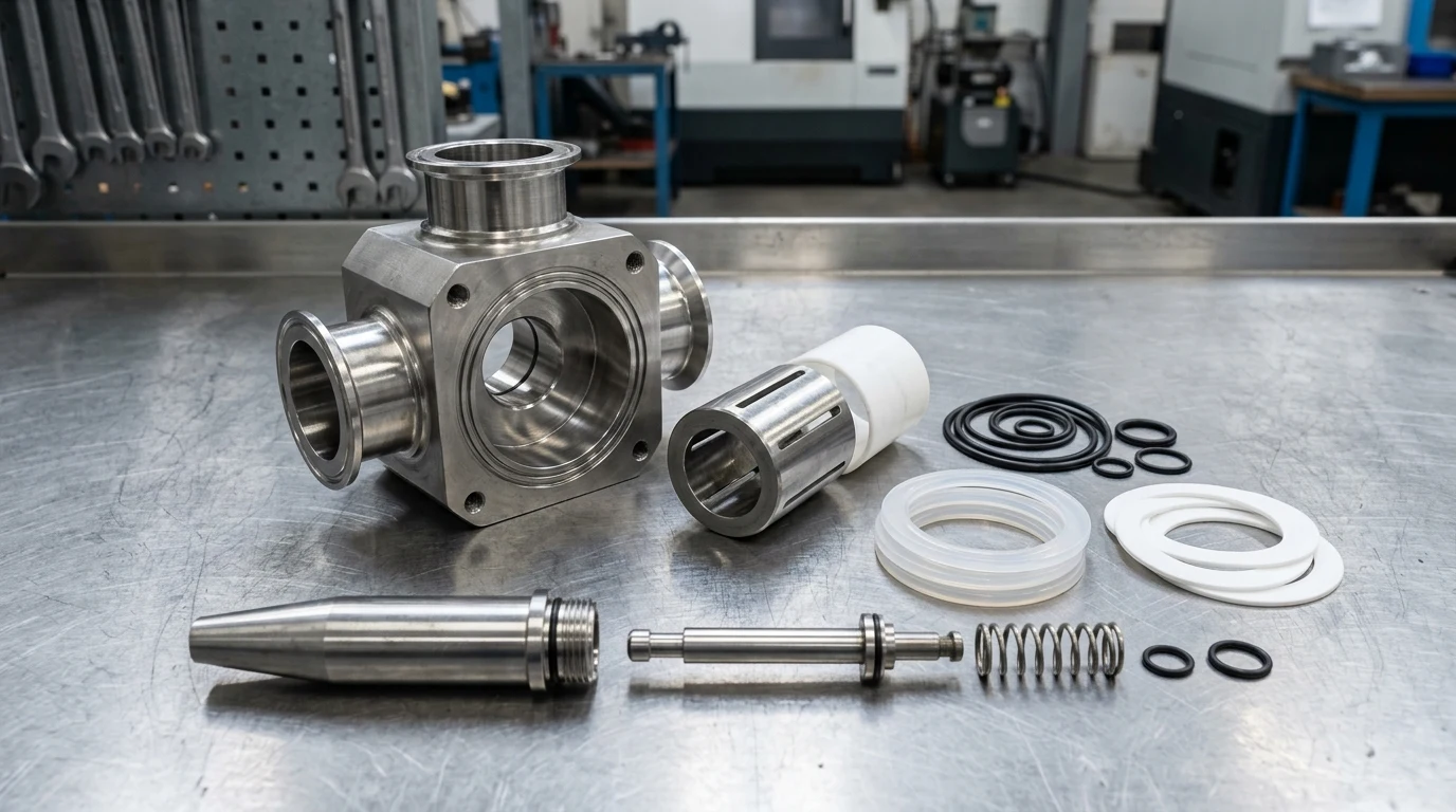
Wear Parts vs Format Parts on a Bottle or Jar Filler
Use this table to classify every item on your request list before contacting the equipment supplier.
| Component group | Wear or service item | Format or change part (swap for new SKU or recipe) | Verification required before ordering |
|---|---|---|---|
| Piston and metering cylinder | Piston wiper rings, PTFE or elastomer piston cups, static cylinder-end O-rings, pneumatic drive cylinder seal kit. | Complete sanitary dose cylinder and matching piston assembly when the new target fill volume falls outside the installed cylinder range. | Confirm both the cylinder capacity model (for example, the specific milliliter series on the unit) and the elastomer compound required for your product and washdown. |
| Directional valve and manifolds | Rotary valve stem O-rings, butterfly valve seat ring, sanitary tri-clamp gaskets, flexible product transfer sleeves. | Chunky-product valve body or wider-passage rotor when switching from smooth paste to sauce with seeds or soft particulates. | Check valve drawing code, ferrule size, and whether particulates require a different valve style rather than a fresh gasket. |
| Filling nozzle and shut-off head | Nozzle tip O-rings, positive shut-off stem seals, removable anti-drip screen inserts that deform during cleaning. | Narrower or wider nozzle tips for a new bottle neck opening; extended bottom-up tubes; honeycomb or positive-off nozzle bodies. | Match nozzle outside diameter to the minimum inner neck opening on your container drawing, and confirm shut-off style against product stringing. |
| Container indexing and support | Conveyor slat-top chain wear strips, side gripper belts, bottle-grabber rubber pads, indexing cylinder cushions. | Star wheels, neck locators, container guide rails, or pucks shaped for a new bottle cross-section or neck height. | Compare container body dimensions and neck finish drawing against existing rail adjustment range before ordering fixed change parts. |
| Controls and stroke sensing | Magnetic reed switches on pneumatic cylinders, proximity sensors, pressure switches, and armoured temperature probes. | Control or service item. Dose, stroke and indexing settings follow the machine manual; a reed switch detects position, while the controller sets timed actions. | Record sensor part marking, thread or clamp mount, cable lead configuration, and machine build year or electrical diagram reference. |
Identify the degraded component on an unchanged configuration before selecting replacement wear items. A new bottle neck, dose window or product texture calls for a format review.
Check Container-Handling Parts Around the Fill Head
Container-handling parts position the opening relative to the nozzle. Inspect bottle grabbers, neck locators, indexing parts, guides and conveyor wear surfaces together. Stiles Enterprises’ Liquid / Paste Filler Replacement Parts groups seals and transfer connectors alongside slat chains and gripping rubbers, reflecting these separate maintenance functions.
When you inspect the filling station, record whether the fill heads are stationary above the conveyor or mounted on a diving carrier, how bottles are stopped under the nozzles (indexing gates, pin indexing kits, or star wheels), and whether neck locators center the container mouth before the nozzle descends. If your line is transitioning from manual bottle placement to indexed conveying, our semi-automatic bottle filling line guide explains how container indexing interfaces with the filler.
Nozzle and Container Location
Check nozzle access and container location together. A change at the neck locator or guide can alter the apparent nozzle fit even when the tip itself is unchanged.
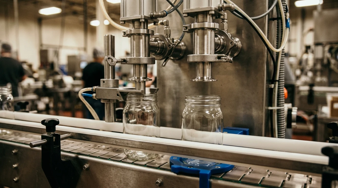
Match the Symptom Before Replacing Nozzle or Seal Parts
Match the symptom to its location before ordering a nozzle or seal kit. After safe isolation, inspect the parts using the machine manual. Post-fill dripping can involve a worn seal, residue at the nozzle, an unsuitable cutoff arrangement or bottle departure before the dose has finished. Check these causes separately.
Before ordering parts for a dripping or inconsistent paste head, clean the valve and nozzle path according to your machine manual and observe where the leak or drip starts. Product leakage near the cylinder or valve stem can involve damaged seals, assembly, mating surfaces or operating conditions. Check each against the service procedure before selecting a replacement. Stringing or tailing at the tip on a newly introduced thick paste points to nozzle shut-off style or suck-back adjustment. Product hitting the jar shoulder instead of the center of the opening points to bottle guide rails, neck locators, or indexing gate timing.
Spare Parts Identification Card: Copy Before Ordering
Use this identification card as the maintenance record for the request. Include the cylinder model and dose range, component drawing and contact-material requirements. Photograph markings and mating parts so the equipment builder can match the assembly.
| Identification field | Where to find it | What to record or photograph | If missing or unreadable |
|---|---|---|---|
| 1. Machine nameplate and build identity | Stamped or etched plate on the main frame or electrical cabinet. | Unblurred photo showing brand, model code, serial number, manufacture date, and configuration revision. | Photograph the full machine from front and rear so the frame style, head count, and control cabinet can be identified. |
| 2. Drawing or spare-parts list code | Original machine manual, exploded assembly drawing, or recommended spare-parts sheet. | Drawing sheet number, callout bubble number, and part code exactly as printed. | Mark unknown and name the product-path zone from the map above (hopper, metering cylinder, valve, manifold, nozzle, or indexing). |
| 3. Part Marking and stamped codes | Laser etching or stamping on pneumatic cylinders, valves, reed switches, motors, or pump bodies. | Close-up photo of any alphanumeric code on the component body or actuator housing. | State that no marking is visible on the component. |
| 4. Two-view component photos with scale | At the station before removal, and on a clean bench after removal (only when safe and covered by your manual). | One photo showing the part installed in place on the station; one photo of the removed part beside a ruler or caliper readings (inner diameter, outer diameter, cross-section or length in mm). | If the part cannot be removed safely without manual instructions, photograph it in place with a ruler held beside the mounting flange or clamp. |
| 5. Function and observed symptom | Operator and maintenance observation during a run. | What the part does on the station and what went wrong (for example: seal extruded at cylinder rear, valve sticking on particulates, or nozzle dripping after shut-off). | Describe whether the issue started gradually on an existing product or immediately after changing product or container. |
| 6. Wetted product and cleaning conditions | Batch sheet and sanitation SOP. | Product type (smooth paste, oily sauce, acidic condiment, or paste with particulates), filling temperature in °C, and cleaning water temperature or chemical agents. | Mark unknown parameters explicitly so the supplier does not guess between EPDM, Viton, Silicone, or PTFE contact materials. |
| 7. Container neck and format drawings (for format parts) | Packaging specification sheet. | Container height, body width/depth, and minimum inner neck opening in mm, with a photo of the bottle or jar. | Measure the container mouth opening and overall height with a ruler and photograph the container beside the scale. |
Takeaway: Four items make a parts request answerable: nameplate identity, drawing or part number, in-place and scaled component photos, and a clear note on function, symptom, and wetted conditions.
Use Drawing Dimensions for the Seal Fit
For a round-section O-ring, geometric squeeze in percent = (effective cross-section − gland depth) / effective cross-section × 100. Use dimensions in the same unit and account for stretch and tolerances when determining the installed section. Parker’s O-Ring Handbook treats squeeze, gland fill and stretch together. Lip seals and piston cups require their own component drawings.
A worn or swollen seal can differ from its original dimensions. Match the replacement to the identified drawing and mating metal geometry, with product and cleaning conditions recorded alongside the part code.
[Sources]
- LINEVO spare parts: machine identification, component records, wear items and format changes. linevopack.com/services/spare-parts
- Piston-filler component options: dose cylinders, nozzles, valve arrangements and bottle indexing. www.accutekpackaging.com/filling-machines/piston-filling-machines/avf12/
- Pneumatic piston motion, directional valve and adjustable stroke on the described semi-automatic filler. hhzpackaging.com/product/semi-automatic-piston-liquid-filling-machine/
- Stirred hopper and piston dosing on the described sauce-filler configuration. hhzpackaging.com/product/semi-automatic-piston-sauce-filling-machine-with-stirrer/
- Filler-parts catalogue organized by component assemblies and machine-specific connections. www.epakmachinery.com/filler-parts/
- Seal kits identified by filler configuration, cylinder capacity and elastomer material. www.epakmachinery.com/seal-kits-apacks/
- Stiles Enterprises Liquid / Paste Filler Replacement Parts: seals, transfer connectors and container-handling items. stilesenterprises.com/pkg_liquid_filler_parts.html
- Filling-machine drip checks: seals, buildup, nozzle style and conveyor timing. www.liquidpackagingsolution.com/news/filling-machines-eliminating-drips
- Parker O-Ring Handbook ORD 5700: round-section O-ring squeeze, stretch and gland design. www.parker.com/content/dam/Parker-com/Literature/O-Ring-Division-Literature/ORD-5700.pdf
Common Engineering Questions: Identifying Paste Filling Machine Parts, Seal Kits & Format Tooling
- 01Can I order a filling machine seal kit by measuring the old O-ring alone?
- Use the original seal drawing and machine parts record alongside the measurement. A used seal can be stretched, worn or swollen. Match the compound and dimensions to the product, cleaning conditions and mating gland.
- 02When is a paste nozzle a wear part versus a format part?
- Internal nozzle O-rings, shut-off stem seals, and deformable screen inserts are wear parts replaced during maintenance. The nozzle body or tip becomes a format part when you switch to a narrower bottle neck, a bottom-up fill path, or a thicker paste that needs a positive shut-off or anti-drip tip.
- 03What if my paste filler has no readable nameplate or spare-parts manual?
- Photograph the complete machine from front and back, the control panel, and the component both installed on the station and beside a millimeter scale, and note the cylinder stroke and port connection sizes. Keep unknown fields marked as unknown until the equipment builder or service technician verifies the assembly.
[Request]
Send Your Station Identification Record
Use the identification card for the parts compatibility discussion. We match the request to the LINEVO or Dession configuration and its parts record.
Our team reviews your product, container and line requirements with you.
[Keep planning]
- Liquid Filling LinesFoam, drip or a narrow bottle opening can make the wrong filler a poor fit. Start with liquid behavior and container dimensions, then match the filling and downstream stations.
- Paste Filling LinesAir and stringing in a paste end up as short fills and dirty seals. Tell us how your product behaves at filling temperature and we configure the feed, dosing and sealing around it.
- HoneyHoney that strings or traps air leaves dirty rims and bubbles in clear jars. Give us the honey state, filling temperature, jar and cap first; they decide the line.
- SaucesParticles that do not suit the bottle opening can block filling or leave sauce on the sealing rim. Match the sauce at filling temperature, its pieces and the container opening before choosing stations.
- Edible OilOil left on the neck after filling weakens the cap seal and the label. Start from the oil and the bottle format; the filler, capper and labeler follow.
- Filling Line CostCompare filling line prices after matching the stations, formats, integration and delivery scope. Then add installation, site work and operating costs on the same accounting basis.
- RFQ ChecklistPrepare a filling line RFQ with the product, container and closure, required accepted output, site layout and delivery scope. A shared brief lets engineering define each station and its interfaces on the same basis.
- Semi-Automatic Bottle LineBuild a semi-automatic bottle filling line by deciding which tasks remain manual and which stations need automatic handling. Review filling, capping, labeling and transfers separately, then plan the interfaces needed for the next upgrade.
- Volumetric vs Net WeightChoose volumetric or net weight filling from the quantity each container must hold. Volume, net product mass and visible fill level are different measurements; define the target unit, tare and product conditions before comparing metering methods.
- Piston vs Gear PumpA piston filler meters through a cylinder stroke; a gear pump filler meters through rotating gears. Compare their product path, valve, seals, dose adjustment and refill behavior with the actual formulation, then connect the selected meter to bottle handling and cleaning.
- Line Speed and Good OutputCompare filling line speed using accepted bottles at the same count point and over the same time window. Separate individual machine cycles from complete-line output, and record stops, rejects and format conditions with the count.
- Cosmetic Bottle Format PlanningPlan cosmetic bottle formats with one record per finished SKU. Product, container, closure, label and the change between SKUs determine which settings, contact parts and handling tools the line needs.