
[Buying guides]
Bottling Line Filler Tube: Bore, Length and the Product That Decides the Spare
Every bottling line filler tube sits at the final boundary between the dosing pump and the container neck. Selecting the right filling machine nozzle tube or liquid filler diving nozzle requires balancing internal bore velocity against annular air escape around the outside of the tube while matching the shutoff tip and elastomer seals to your liquid viscosity.
Updated November 2026
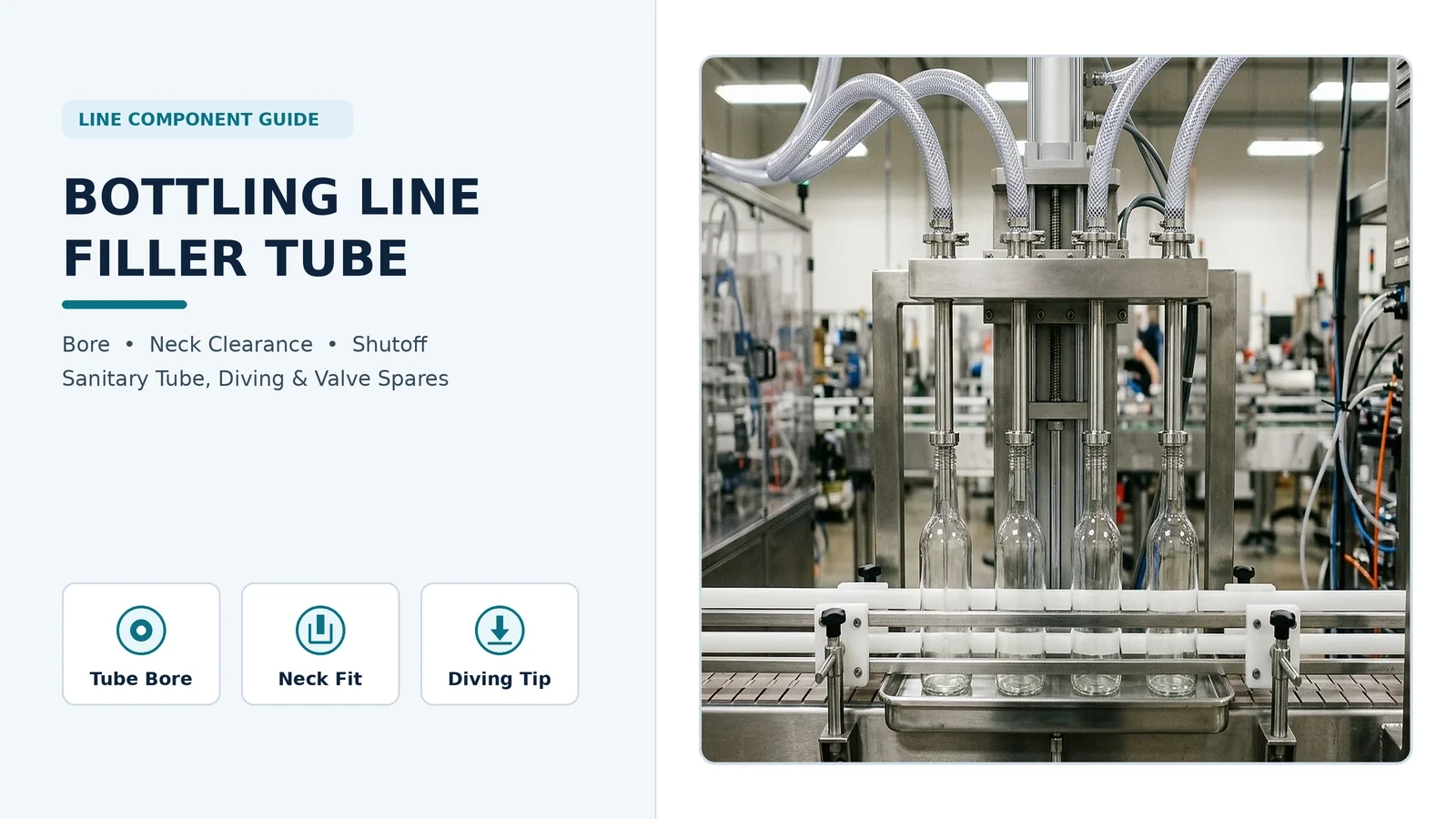
Bottling Line Filler Tube Architecture: Capillary, Positive Shutoff, and Overflow Designs
We engineer each bottling line filler tube and manifold assembly around your container neck finish, liquid rheology, and target line speed across our liquid filling lines.
Filling nozzles, also called filling needles or filling tubes, are the discharge point of the filler where product enters the container and most are variations on three basic types: capillary, inward opening, and outward opening.
A larger nozzle diameter gives lower product velocity for a given flow rate (reducing foaming, splashing, and agitation), while the nozzle must be small enough to allow displaced air to escape through the annular opening between the nozzle and container.
A capillary nozzle is a plain section of tubing that typically has no internal valving; the filling system normally uses an upstream shutoff valve, and capillary action (surface tension) prevents product dripping from the end of the nozzle.
If vibration or shock at a capillary nozzle or tubing may break surface tension, product in the nozzle and tubing may run out, causing an overfill in the current container or a mess on the filling machine, and an underfill on the next bottle because the nozzle and tubing are empty.
Side-shooting capillary nozzles have a closed bottom end and horizontal openings near the nozzle end that reduce discharge velocity and direct product against the container wall to reduce foaming, agitation, and splashing.
Multiple-channel nozzles use a concentric tube-in-tube design or two, usually half-round, tubes mounted back to back; overflow fillers use one channel for product and a second channel to vent air from the bottle as it fills.
Volumetric Technologies overflow nozzles dive into the container and are compressed open to allow product flow; when the container is full and overflows into the return line, the nozzle retracts and product flow is shut off.
Positive Shutoff Nozzles (PSNs) have inward- or outward-opening valves inside the nozzle near the tip; a slight closing delay of 100-200ms after the pump stops may be used to break a product string.
On a positive shutoff nozzle, if the valve is closed when the pump begins or closes before the end of filling, excessive pressure can rupture the product tubing, so a sensor is recommended to inhibit filling if the valve is not open.
Some positive shutoff nozzles have a hollow operating rod that allows connection of vacuum, nitrogen or other gas; vacuum may be enabled to suck product out/off the nozzle end; outward-opening nozzles often have a pointed tip so residual product on the outside flows toward the center vacuum hole; alternately a puff of nitrogen or air may be used to blast residual strings loose.
Upstream metering choices that feed these nozzle assemblies are compared in our piston vs gear pump filling guide.
Filling Equipment Company (Wabash Equipment) specifies straight-through open-tip nozzles with 20 to 100 mesh wire screens at the tip for non-foaming liquids (0.5 - 50 cP), positive shut-off internal plug nozzles for 50 - 800 cP, sub-surface diving nozzles for 800 - 5,000 cP, and full-port straight viscous nozzles for 5,000 - 50,000+ cP.
Volumetric Technologies manufactures 316L stainless steel dispensing nozzles in specific opening diameter ranges by style: Beveled Seat bottom shut-off nozzles (.25" to 1.9"), Inverted Cone nozzles (.375" to 4"), Rotary Cutoff nozzles (1" - 3"), and Plug Spout nozzles (.375" up to 3").
Brenu Filling notes that a nozzle opening only slightly larger than the largest expected particle may still clog when several particles enter the restriction simultaneously, and installing a large-bore nozzle provides little benefit if an upstream valve contains a smaller restriction.
Liquid Viscosity and Product Behavior to Filling Machine Nozzle Tube Selection
Match your liquid viscosity bracket and particulate or foaming behavior to the corresponding filling machine nozzle tube architecture and opening diameter range.
| Product Viscosity or Duty | Recommended Nozzle Tube Architecture | Cut-Off and Flow Control Mechanism | Published Opening or Mesh Range |
|---|---|---|---|
| Non-foaming thin liquids (0.5 - 50 cP) | Straight-through open-tip nozzle tube | Tip wire-mesh screens creating a surface-tension barrier | 20 to 100 mesh wire screens at the tip |
| Medium-viscosity liquids (50 - 800 cP) | Positive shut-off internal plug nozzle | Inward/outward tip plug valve with 100-200 ms closing delay or vacuum/air string cutoff | 0.25" to 1.9" beveled seat or 0.375" to 3" plug spout |
| Viscous or foaming liquids (800 - 5,000 cP) | Sub-surface liquid filler diving nozzle | Synchronized slow-fast-slow bottom-up nozzle lift with drip tray or suckback channel | 3/8" to 1-1/2" bottom-close Tri-Clamp or 11/16" dual-screen de-foaming tip |
| Heavy pastes and viscous products (5,000 - 50,000+ cP) | Full-port straight viscous nozzle | Inverted-cone or rotary cutoff spool matched to upstream valve bore | 0.375" to 4" inverted cone or 1" to 3" rotary cutoff |
Filling machine nozzle tube selection by viscosity range, tip shutoff design, and opening size.
Sanitary Filling Machine Nozzle Tube Bore, Wall, and Tri-Clamp Ferrule Dimensions
According to ASME BPE Table DT-4.1, 1/4" nominal sanitary tubing (part 130.A-025.WEL.XX.XXX) has an outside diameter (AD) of 6.35 mm, an inside diameter (ID) of 4.57 mm, and a wall thickness (S) of 0.89 mm.
According to ASME BPE Table DT-4.1, 3/8" nominal sanitary tubing (part 130.A-0375.WEL.XX.XXX) has an outside diameter (AD) of 9.53 mm, an inside diameter (ID) of 7.75 mm, and a wall thickness (S) of 0.89 mm.
According to ASME BPE Table DT-4.1, 1/2" nominal sanitary tubing (part 130.A-050.WEL.XX.XXX) has an outside diameter (AD) of 12.70 mm, an inside diameter (ID) of 9.40 mm, and a wall thickness (S) of 1.65 mm.
According to ASME BPE Table DT-4.1, 3/4" nominal sanitary tubing (part 130.A-075.WEL.XX.XXX) has an outside diameter (AD) of 19.05 mm, an inside diameter (ID) of 15.75 mm, and a wall thickness (S) of 1.65 mm.
According to ASME BPE Table DT-4.1, 1" nominal sanitary tubing (part 130.A-100.WEL.XX.XXX) has an outside diameter (AD) of 25.40 mm, an inside diameter (ID) of 22.10 mm, and a wall thickness (S) of 1.65 mm.
According to ASME BPE Table DT-4.1, 1"1/2 nominal sanitary tubing (part 130.A-150.WEL.XX.XXX) has an outside diameter (AD) of 38.10 mm, an inside diameter (ID) of 34.80 mm, and a wall thickness (S) of 1.65 mm.
According to Penn Stainless ASME BPE specifications, 1/2" (12.7 mm), 3/4" (19.1 mm), and 1" (25.4 mm) OD tubes have an OD tolerance of +/-0.005" (0.13 mm), a wall thickness of 0.065" (1.65 mm), and a wall thickness tolerance of +/-10.0%.
In Penn Stainless ASME BPE flow tables, 1/2" OD tubing (0.37" ID, 0.065" wall) holds 0.56 Gal/100 ft and delivers 1.7 GPM at 5 fps, 2.3 GPM at 7 fps, and 3.4 GPM at 10 fps mean velocity.
In Penn Stainless ASME BPE flow tables, 3/4" OD tubing (0.62" ID, 0.065" wall) holds 1.57 Gal/100 ft and delivers 4.7 GPM at 5 fps, 6.6 GPM at 7 fps, and 9.4 GPM at 10 fps, while 1" OD tubing (0.87" ID, 0.065" wall) holds 3.09 Gal/100 ft and delivers 9.3 GPM at 5 fps, 13 GPM at 7 fps, and 19 GPM at 10 fps.
Brenu Filling shows that for a 1 L bottle, if available actual filling time is 4 seconds, the required average delivery rate during filling is approximately 15 L/min per active nozzle, and reducing filling time to 2 seconds roughly doubles that requirement.
Quick-release ferrule connections at the top of the filler tube also follow shared flange groups across adjacent tube diameters.
According to ASME BPE DT-4.1.4-1 B Series (Standard Version), 1/4" (6.35 mm AD, 4.57 mm ID) and 3/8" (9.53 mm AD, 7.75 mm ID) Tri-Clamp ferrules share a 25.00 mm flange outside diameter (A) and 28.58 mm length (L).
According to ASME BPE DT-4.1.4-1 B Series (Standard Version), 1/2" (12.70 mm AD, 9.40 mm ID) and 3/4" (19.05 mm AD, 15.75 mm ID) Tri-Clamp ferrules also share the same 25.00 mm flange outside diameter (A) and 28.58 mm length (L).
According to ASME BPE DT-4.1.4-1 B Series (Standard Version), both 1" (25.40 mm AD, 22.10 mm ID) and 1"1/2 (38.10 mm AD, 34.80 mm ID) Tri-Clamp ferrules share a 50.50 mm flange outside diameter (A) and 28.58 mm length (L).
According to ASME BPE DT-4.1.4-1, C Series (Short Version) 1/2" (12.70 mm AD, 9.40 mm ID) and 3/4" (19.05 mm AD, 15.75 mm ID) Tri-Clamp ferrules with a 25.00 mm flange have a length (L) of 12.70 mm, whereas A Series (Long Version) 1/2" and 3/4" ferrules have a length (L) of 44.45 mm.
Filling Equipment Company states that 3-A Sanitary compliant CIP/SIP Tri-Clamp nozzles use electropolished internal bores with surface roughness Ra < 0.4 µm, and replacing threaded nozzle assemblies with quarter-turn bayonet or toolless Tri-Clamp nozzles reduces changeover downtime from 45 minutes to under 5 minutes.
ASME BPE Sanitary Filler Tube Dimensions, Ferrule Flanges, and Flow Capacity
Reference these standard sanitary tube outside diameters, internal bores, wall thicknesses, Tri-Clamp ferrule flange diameters, and mean-velocity flow rates when sizing a bottling line filler tube.
| Nominal Tube Size | Outside Diameter (AD) & Bore (ID) | Wall Thickness (S) | B Series Ferrule Flange (A) & Length (L) | Mean-Velocity Flow Rate | Catalog Part Reference |
|---|---|---|---|---|---|
| 1/4" nominal sanitary tubing | 6.35 mm AD / 4.57 mm ID | 0.89 mm wall | 25.00 mm flange / 28.58 mm length (DT-4.1.4-1) | - | 130.A-025.WEL.XX.XXX (DT-4.1) |
| 3/8" nominal sanitary tubing | 9.53 mm AD / 7.75 mm ID | 0.89 mm wall | 25.00 mm flange / 28.58 mm length (DT-4.1.4-1) | - | 130.A-0375.WEL.XX.XXX (DT-4.1) |
| 1/2" nominal sanitary tubing | 12.70 mm AD / 9.40 mm ID (0.37" ID) | 1.65 mm (0.065" wall) | 25.00 mm flange / 28.58 mm length (12.70 mm C Series, 44.45 mm A Series) | 1.7 GPM / 2.3 GPM / 3.4 GPM (0.56 Gal/100 ft) | 130.A-050.WEL.XX.XXX (DT-4.1) |
| 3/4" nominal sanitary tubing | 19.05 mm AD / 15.75 mm ID (0.62" ID) | 1.65 mm (0.065" wall) | 25.00 mm flange / 28.58 mm length (12.70 mm C Series, 44.45 mm A Series) | 4.7 GPM / 6.6 GPM / 9.4 GPM (1.57 Gal/100 ft) | 130.A-075.WEL.XX.XXX (DT-4.1) |
| 1" nominal sanitary tubing | 25.40 mm AD / 22.10 mm ID (0.87" ID) | 1.65 mm (0.065" wall) | 50.50 mm flange / 28.58 mm length (DT-4.1.4-1) | 9.3 GPM / 13 GPM / 19 GPM (3.09 Gal/100 ft) | 130.A-100.WEL.XX.XXX (DT-4.1) |
| 1"1/2 nominal sanitary tubing | 38.10 mm AD / 34.80 mm ID | 1.65 mm wall | 50.50 mm flange / 28.58 mm length (DT-4.1.4-1) | - | 130.A-150.WEL.XX.XXX (DT-4.1) |
Sanitary filler tube outside diameter, internal bore, wall thickness, Tri-Clamp ferrule flange geometry, and flow rates.
Matching Filler Tube Outer Diameter to Container Neck Finish Clearance
Even when a filling machine nozzle tube has the internal bore needed for target cycle time, its outer tip envelope must pass cleanly inside the bottle mouth without choking off escaping air or striking the inner neck wall.
In our bottling line configurations, nozzle access checks compare the minimum neck opening with the nozzle envelope through entry and withdrawal while keeping the bottle located during dosing.
As a general engineering rule stated by Filling Equipment Company (Wabash Equipment), the nozzle tip outer diameter (OD) should be at least 1.5 mm to 2.0 mm smaller than the smallest inside diameter (ID) of the container neck finish so displaced air can exhaust freely during filling.
Lancing Ltd (bottlefillingmachines.co.uk) states that nozzle-to-neck clearance is specified from actual outside nozzle size, bottle opening, positional tolerance, bottle movement, and required insertion depth because moulded bottles vary and empty containers can lean or flex under guide pressure.
In GPI/SPI container neck finish specifications, the "I" dimension is the inner diameter of the bottle neck, and specifications require a minimum "I" to allow sufficient clearance for filling tubes and proper fit for linerless closures and dispensing plugs.
In GPI/SPI container neck finish specifications, the "T" dimension is the outside diameter of the thread (whose tolerance range determines the mate between bottle and closure), and the "E" dimension is the outside diameter of the neck (where the difference between "E" and "T" divided by two determines thread depth).
In GPI/SPI container neck finish specifications, the "H" dimension is the height of the neck finish measured from the top of the neck to the point where the diameter "T," extended down, intersects the shoulder, and the "S" dimension is measured from the top of the finish to the top edge of the first thread.
In standard continuous-thread neck finishes, 400 indicates one thread turn, 410 indicates one and a half turns, 415 indicates two thinner thread turns on a typically taller neck, 425 indicates two thread turns most commonly found on smaller-capacity containers such as vials, and 430 indicates one or two deeper buttress thread turns.
Common GPI/SPI neck finishes by bottle capacity range include 18-400 (essential oil dropper bottles), 20-410 (mainly found on bottles ranging from 1oz to 4oz), 24-410 (found in a variety of bottle sizes ranging from 2oz to 16oz), 28-410 (found in a variety of medium bottles ranging from 8oz to 32oz), and 38-400 (sizes ranging from 4oz to 1 gallon bottles).
Within a nominal 28 mm bottle diameter, at least four non-interchangeable thread families exist: PCO / ISBT carbonated-beverage finishes (PCO 1881, PCO 1810, PCO 1817, PCO 1823), SP PET water-bottle finishes (SP 400, SP 410, SP 415, SP 425, SP 430), Alcoa, and Obrist.
GPI (glass) and SPI (plastic) use the same notation (such as 24-410) for different standards: plastic bottle finishes are specified under ASTM D2911/D2911M ("Dimensions and Tolerances for Plastic Bottles"), whereas glass finishes are governed by GPI finish drawings.
Additional container geometry checks across narrow-neck bottles and wide-mouth jars are covered in our bottle filling line format checks guide and jar filling line neck and closure guide.
Compare Wide-Bore Viscous Nozzle Fit Against Slender Narrow-Neck Filler Tube Entry
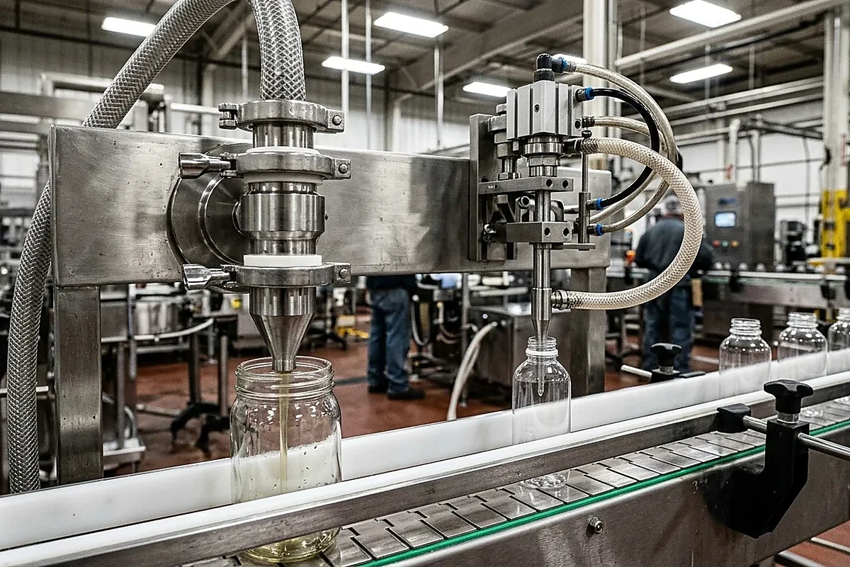
Liquid Filler Diving Nozzle Stroke Length, Rise Profile, and Foam Control
When surfactant cleaners or shampoos foam under top-fill free-fall, a liquid filler diving nozzle descends to a programmed near-base starting height, then filling begins, and the nozzle rises with the liquid surface during dosing.
Line-level foam and surfactant handling checks are detailed in our liquid detergent filling line checks guide.
When a filling nozzle is submerged in the product, product drips from the outside of the nozzle rather than the inside and can only be captured via a drip tray or a suckback channel in the nozzle.
King Pack states that in a diving-nozzle filling cycle, if the nozzle rises too quickly during dispensing, free-fall and foaming return; if it rises too slowly, the nozzle may be submerged too deeply, increasing back pressure or carrying product on its exterior.
JPACKS JPF Series automatic inline servo piston fillers provide touchscreen-adjustable automatic nozzle lift where nozzles operate above the bottle mouth or in bottom-up mode synchronized with the liquid level, with a slow-fast-slow speed profile, 304 or 316L contact parts, 0.4-0.6Mpa air pressure, and claims to outperform competitors' ±0.5-1% fill-level precision.
E-PAK Machinery's 1/2" De-foaming Nozzle Assembly (SKU 5002-038) has a 1/2" NPT thread, 11/16" tip opening, 3 3/16" height, polyethylene construction, .01 LBS weight, and two internal stainless steel screens: one 1/2" fine screen (1107-015) and one 3/4" fine screen (1107-006).
Synchronize Multi-Head Diving Nozzle Descent With Bottle Neck Positioning
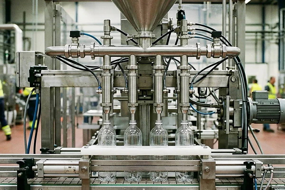
Wetted Metallurgy, Surface Finish, and Elastomer Seal Selection
Wetted tube metallurgy, internal bore polish, and valve seal compounds govern cleanability, chemical resistance, and wear life inside a bottling line filler tube.
According to Dockweiler ASME BPE specifications, 316L stainless steel grades UNS S31603 (316L) and 1.4435 have a defined sulfur content of 0.005 - 0.017%, and 316L stainless steel (UNS S31603 / 1.4404 / 1.4435) has hardness equivalent to maximum 180 HV (DIN EN ISO 6507-1) or maximum 90 HRB (DIN EN ISO 6508-1).
Under ASME BPE Part SF (Table SF-2.4.1-1), mechanically polished surface designation SF1 specifies Ra max of 20 µin (0.51 µm), and electropolished designation SF4 specifies Ra max of 15 µin (0.38 µm), with Ra readings in accordance with ASME B46.1.
Across our filling and packaging machines, we classify seals and O-rings in pumps and nozzles among typical wear parts, whereas manifold pitch and guiding parts change when the container format width changes.
Under 21 CFR § 177.2600, rubber articles intended for repeated use may be safely used in producing, manufacturing, packing, processing, preparing, treating, packaging, transporting, or holding food.
Under 21 CFR § 177.1550, perfluorocarbon resins produced by the homopolymerization and/or copolymerization of hexafluoropropylene and tetrafluoroethylene, or by the copolymerization of perfluoropropylvinylether and tetrafluoroethylene (CAS Registration No. 26655-00-5), may be safely used as articles or components of articles intended to contact food.
Inspect Tapered Filler Tube Tips, Shutoff Stems, Tri-Clamp Ferrules, and Seal Kits
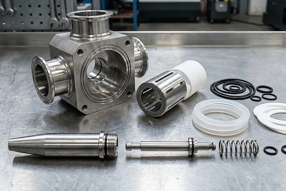
Identifying and Specifying Replacement Filler Tubes and Spare Nozzle Assemblies
Ordering a replacement bottling line filler tube or nozzle tip requires matching both the upper mounting thread or Tri-Clamp ferrule and the lower tip outer diameter.
For broader valve core and seal kit identification on viscous fillers, see our paste filling machine parts identification guide.
In E-PAK Machinery's replacement nozzle tip catalog, APACKS piston filler nozzle tips with an 18MM THREAD are stocked in 6MM, 8MM, 10MM, and 12MM tip diameters, while APACKS nozzle tips with a 24MM THREAD are stocked in 10MM, 12MM, 14MM, 16MM, and 18MM tip diameters.
E-PAK Machinery's Bottom Close Nozzle (Internal) assembly uses a 1" & 1 1/2" Tri-Clamp size, a 3/8" to 1-1/2" nozzle size range, 1/4" air tube ports, air cylinder 1113-251, flow control air fitting 1123-100 or 1124-183, and Tri-Clamp gasket 1125-100.
E-PAK Machinery stocks a 3/4" Tri-Clamp flow-restrictor gasket with a 1/8" center opening designed to slow down product flow and be reamed out to match the operator's flow preference.
Our LINEVO spare-parts identification procedure requires the machine nameplate, model, serial number, configuration revision, a component photo, part marking, and its function on the machine.
Our spare-parts guidance also requires the part number from the spare parts list or drawing if available, plus photos of the part in place and removed with a ruler or dimensions.
Pre-RFQ Measurement Checklist for Bottling Line Filler Tube Spares
Record these physical measurements and container details before ordering replacement filling machine nozzle tubes or configuring a new manifold.
- Machine nameplate, model, serial number, configuration revision, part number from the spare parts list or drawing, and photos of the filler tube in place and removed alongside a ruler.
- Upper manifold connection style and dimensions: Tri-Clamp ferrule flange outside diameter and ferrule length or threaded body size.
- Tube outer diameter, internal bore diameter, wall thickness, overall tube length, and required diving insertion depth into the bottle.
- Container neck finish standard, thread series, and minimum neck inner diameter so annular air-escape clearance is verified before fabrication.
- Tip shutoff architecture (open capillary tube, side-shooting ports, concentric overflow tube, internal plug positive shutoff, or dual-screen de-foaming assembly) and wetted seal compound.
- Compile your complete container, product, and line rate parameters with our filling line RFQ checklist when requesting a turnkey filling line proposal.
Sources
- LINEVO PACK: Spare and Change Parts Identification Procedure for Packaging Equipment
- Our LINEVO Engineering Library: Liquid Filling Lines Engineering and Nozzle Access Reference
- Frain Group and John R Henry: Liquid Filling Nozzles Technical White Paper
- Aseptconn AG: Sanitary Tubes and Tri-Clamp Ferrules Product Catalog
- Dockweiler AG: Stainless Steel Sanitary Tube Material and Surface Specification
- Penn Stainless Products: Sanitary Tube Tolerances and Velocity Flow Tables
- C.L. Smith: Container Neck Finish Dimensions Technical Guide
- Paramount Global: Bottle Neck Finishes, Thread Series, and Capacity Reference
- Daxin Glass: Glass and Plastic Bottle Neck Finish Standards Comparison
- Electronic Code of Federal Regulations: Food-Contact Rubber Articles and Perfluorocarbon Resins
- Filling Equipment Company (Wabash Equipment): Industrial Liquid Filling Nozzles Selection Guide
- Volumetric Technologies: Stainless Steel Liquid Filling Nozzles and Dispensers Specification
- Brenu Filling: Liquid Filling Nozzle Selection and Flow Rate Engineering Guide
- E-PAK Machinery: Replacement Filler Nozzle Tips, Bottom-Close Nozzles, and De-Foaming Assemblies Catalog
- Lancing Ltd: Bottle Filling Nozzles, Diving Stroke, and Neck Clearance Guide
- King Pack: Bottom-Up Diving Nozzle Foam Control Technical Guide
- JPACKS: Automatic Inline Servo Piston Filler Nozzle Lift Specification
Frequently Asked Questions
- 01How much clearance is required between a bottling line filler tube and the bottle neck?
- Size the filler tube tip outer diameter (OD) at least 1.5 mm to 2.0 mm smaller than the minimum container neck inside diameter (the GPI/SPI "I" dimension). This annular gap allows displaced air to vent freely while accounting for molded bottle neck tolerances, guide-rail bottle lean, and diving insertion depth.
- 02When should a liquid filler diving nozzle be used instead of a top-fill nozzle tube?
- Use a bottom-up diving nozzle for foaming surfactants or viscous liquids in the 800-5,000 cP range. The tube lowers near the container floor before dosing and rises in sync with the rising liquid level (using a slow-fast-slow servo profile) so the tip neither outruns the surface (causing free-fall foam) nor submerges too deeply (where product clings to the outer tube wall and requires a drip tray or suckback channel).
- 03Do adjacent sanitary filler tube sizes use the same Tri-Clamp ferrule flange size?
- Yes. Under ASME BPE DT-4.1.4-1 B Series, 1/4" (6.35 mm OD / 4.57 mm ID), 3/8" (9.53 mm OD / 7.75 mm ID), 1/2" (12.70 mm OD / 9.40 mm ID), and 3/4" (19.05 mm OD / 15.75 mm ID) sanitary tubes all mate to a 25.00 mm Tri-Clamp ferrule flange (28.58 mm standard B-series length), while 1" (25.40 mm OD / 22.10 mm ID) and 1-1/2" (38.10 mm OD / 34.80 mm ID) tubes share a 50.50 mm ferrule flange.
- 04What information is needed to identify a replacement filling machine nozzle tube or seal kit?
- Send our engineering team the machine nameplate, model, serial number, spare-parts drawing number, and photos of the filler tube both installed and removed next to a scale ruler. Include the upper mounting geometry - such as a 25.00 mm or 50.50 mm Tri-Clamp ferrule, or an 18 mm thread (6/8/10/12 mm tips) versus a 24 mm thread (10/12/14/16/18 mm tips) - plus tube OD/ID, overall length, tip shutoff style, and O-ring/gasket material.
[Request]
Send Your Bottle Neck Drawing, Product Viscosity, and Filler Tube Dimensions
Share your container neck finish drawing, liquid viscosity and foaming behavior, target fill volume, and current nozzle photos on WhatsApp so our engineering team can specify the matching bottling line filler tube and manifold configuration.
Our team reviews your product, container and line requirements with you.
[Keep planning]
- Liquid Filling LinesFoam, drip or a narrow bottle opening can make the wrong filler a poor fit. Start with liquid behavior and container dimensions, then match the filling and downstream stations.
- RFQ ChecklistPrepare a filling line RFQ with the product, container and closure, required accepted output, site layout and delivery scope. A shared brief lets engineering define each station and its interfaces on the same basis.
- Piston vs Gear PumpA piston filler meters through a cylinder stroke; a gear pump filler meters through rotating gears. Compare their product path, valve, seals, dose adjustment and refill behavior with the actual formulation, then connect the selected meter to bottle handling and cleaning.
- Liquid Detergent Line ChecksPlan a liquid detergent filling line around the formulation, foam behavior, bottle geometry and closure. Review the fill motion, product-contact materials, bottle support and capping handoff together, using samples at the intended filling condition.
- Paste Filler Parts IdentificationIdentify paste filling machine parts by the machine record, the component function and the product path. Separate wear seals from valve hardware and format parts, then check the drawing and material before ordering a replacement.
- Jar Neck and ClosureBring the jar drawing, product-piece details and cap specification into the same line brief. Work through the opening, cut-off and closing checks before requesting a configuration.
- Bottle Format ChecksPrepare the body, neck and closure drawings, then use the format-confirmation sheet to review positioning, settings and change parts across the proposed line.